


3-6 Machine Maintenance Procedures
Maintenance Flowchart 0
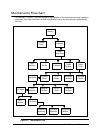
The flowchart in Figure 3-1 provides a graphic representation of the module removal and installation
sequences. It provides information on what components need to be removed and installed during
servicing.
Figure 3-1. Maintenance Flow
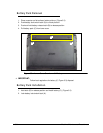
Battery
Dummy
Card
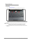
Keyboard
Lower
Cover Door
DIMM
Module
Upper
Cover
WLAN
HDD
Module
3G Module
Touchpad
Board
Bluetooth
Module
Function
Board
Mainboard
Thermal
Module
DC-IN
Cable
Speaker
Module
LCD
Module
LCD Bezel
LCD Panel
LCD Panel
Brackets
3G&WLAN
Antennas
Microphone
Module
RTC
Battery
CCD
Module