


Chapter 4 99
1. Boot from the diagnostics diskette and start the diagnostic program (please refer to main board.
2. Go to the diagnostic memory in the test items.
3. Press F2 in the test items.
4. Follow the instructions in the message window.
Note: Make sure that the DIMM is fully installed into the connector. A loose connection can cause an error.
Power System Check
To verify the symptom of the problem, power on the computer using each of the following power sources:
1. Remove the battery pack.
2. Connect the power adapter and check that power is supplied.
3. Disconnect the power adapter and install the charged battery pack; then check that power is supplied by the
battery pack.
If you suspect a power problem, see the appropriate power supply check in the following list:
q “Check the Power Adapter” on page 99
q “Check the Battery Pack” on page 99
Check the Power Adapter
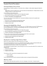
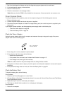
Unplug the power adapter cable from the computer and measure the output voltage at the plug of the power
adapter cable. See the following figure
1. If the voltage is not correct, replace the power adapter.
2. If the voltage is within the range, do the following:
q Replace the System board.
q If the problem is not corrected, see “Undetermined Problems” on page 115.
q If the voltage is not correct, go to the next step.
Note: An audible noise from the power adapter does not always indicate a defect.
3. If the power-on indicator does not light up, check the power cord of the power adapter for correct continuity and
installation.
4. If the operational charge does not work, see “Check the Battery Pack” on page 99.
Check the Battery Pack
To check the battery pack, do the following:
From Software:
1. Check out the Power Management in control Panel
2. In Power Meter, confirm that if the parameters shown in the screen for Current Power Source and Total Battery
Power Remaining are correct.
3. Repeat the steps 1 and 2, for both battery and adapter.
4. This helps you identify first the problem is on recharging or discharging.
From Hardware:
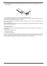
1. Power off the computer.
Pin 1: +19 to +20.5V
Pin 2: 0V, Ground