


73
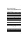
• The following FBDIMM slots must be identical in organization,
size and speed.
• The following DIMM slots need not be identical in
organization, size and speed.
• Sparing should be enabled in the BIOS setup utility
• BIOS will configure rank sparing mode.
• The largest memory size among the DIMM pairs (DIMM_A1,
DIMM_B1) and (DIMM_A2, DIMM_B2) and (DIMM_C1,
DIMM_D1) and (DIMM_C2, DIMM_D2), will be selected as the
spare pair units.
Note: After upgrading system memory to this feature, the
memory RAS setting in the BIOS setup must be set to Sparing
configuration. Refer to the BIOS setup’s Configure Memory RAS
and Performance screen on page 101 for more information.
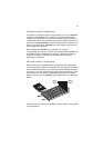
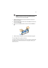
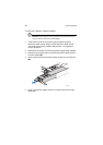
To install FBDIMMs:
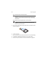
Caution! Use extreme care when installing a FBDIMM. Applying
too much pressure can damage the connector. FBDIMMs are keyed
and can be inserted in only one way.
Note: The number labels next to the FBDIMM slots correspond to
proper installation sequence.
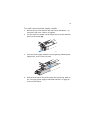
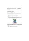
1 Observe the ESD precautions and pre-installation instructions
described on page 39.
2 Remove the CPU air duct. Perform the instructions described in “To
remove the CPU air duct” section on page 45.
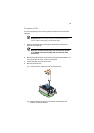
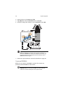
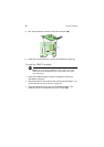
3 Locate the DIMM slots on the mainboard.
• DIMM slots A1 and B1 • DIMM slots C1 and D1
• DIMM slots A2 and B2 • DIMM slots C2 and D2
• DIMM slots A1 and A2 • DIMM slots C1 and C2
• DIMM slots B1 and B2 • DIMM slots D1 and D2