


1. Product Specification (continued)
1.3.1.3 Audio Jack (option)
This jack shall connect the audio input from
host computer.
1.3.2 Video Input Signals
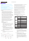
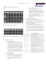
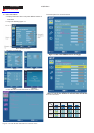
D-SUB PinDescription
Pin Name Description
1 Red-Video Red video signal input.
2 Green-Video Green video signal input.
3 Blue-Video Blue video signalinput.
4GND Ground
5 DDC-GND DDC ground for the VESA DDC2Bifunction.
6 Red-GN D Analog signal ground for the Red video.
7 Green-GN D Analog signal ground for the Greenvideo.
8 Blue-GN D Analog signal ground for the Blue video.
9 + 5V + 5V input from host system fo rthe V ES A DD C 2 Bifunction.
1 0 S ync -GND S ignalgro und
11 GND Ground
12 DDC_SDA SDA signalinput for the VESA DDCB2i function.
13 H -S YN C H orizontalsignalinputfrom the host system.
1 4 V - S Y NC V e rtica lsignalinput from the ho st sys tem .
15 DDC-SC L SCL signalinput forthe VESA DDC2Bifunction.
Connector Pin Description
1.3.2.1 Video Signal Amplitudes
The three video inputs consist of Red , Green ,
and Blue signals, each with its own coaxial cable
terminated at the monitor. These video signals are
analog levels, where 0 V corresponds to black ,
and 700 mV is the maximum signal amplitude for
the respective color, when each signal is
terminated by a nominal 75.0 ohms .For a given
monitor luminance levels are measured using this
defined video amplitude driving a monitor meeting
the termination requirements . The signal
amplitude is not to be readjusted to compensate
for variations in termination impendence.
1.3.2.2 Video Signal Termination Impedance
This analog video signal termination shall be 75
1% which shall be resistive with a negligible reactive
component.
1.3.2.3 Synchronization ( Sync ) Signals
The Horizontal Sync (HS) TTL signal is used to initiate
the display of a horizontal line. HS may be either active
high or active low, depending upon the timing .The
Vertical Sync (VS) TTL signal is used to initiate the
display of a new frame .VS may be either active high or
active low, depending on the timing .
1.3.2.4 Sync Signal Levels
The monitor must accept sync signals from both 3.3 and
5 volt TTL logic families.The inputs shall sense a logic 0
when the input is 0.8 volt or less and shall sense a logic
1 when the input is 2.0 volts or greater. In addition to
these level requirements , there shall also be a
minimum of 0.3 volt hysteresis provided for noise
immunity (typically by using a Schmitt Trigger input ).
That is , the input level at which the monitor actually
detects a logic 0 shall be at least 0.3 volt lower than the
level at which it actually detects a logic 1.If the monitor
sync processing circuits are designed around the 3.3
volt logic family ,then the sync inputs must be 5 volt
tolerant .
1.3.2.5 Sync Signal Loading
TTL input loading shall be equivalent to one TTL input
load. When logic 0 is asserted by a sync input , the
maximum current source from any single monitor sync
input to the driver is 1.6 mA .When logic 1 is asserted ,
the maximum current source from the driver to any
single monitor sync input is 400 uA .
1.3.2.6 Abnormal Signal Immunity
The monitor shall not be damaged by improper sync
timing , pulse duration , or absence of sync , or
abnormal input signal amplitude ( video and/ or sync too
large or too small) , or any other anomalous behavior of
a graphics card video generator when changing modes
, or when any combination of input signals is removed
or replaced . Additionally , under these conditions , the
monitor shall not cause damage to the driving source .
Ω
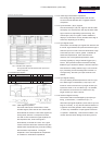
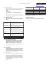
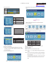
NO. Symbol Item Min NormalMax Unit Remark
1 Fh ScanningHorizontalFrequency 31 94 kHz MinimumRange
2 Fv ScanningVerticalFrequency 50 75 Hz MinimumRange
3 Vih Hi LevelInput 2 5 Note1)
4 Vil LowLevelInput 0 0.8 V Note1)
5 Video RGBAnalogVideoLevel 0.0 0.7 1.0 V 75? toGround
Note1)Schmitt-TriggersInput,Supported3.3VdeviceH (&V)syncoutputfromPC
3
Go to cover page
ACER H233H