


ADCP-80-524 • Issue 1 • November 2001
Page 13
© 2001, ADC Telecommunications, Inc.
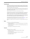
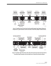
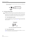
1.9 Power-On Indicator
A visual power-on indicator (green LED) for each power bus is mounted on the front panel of
the fuse panel. A lighted LED indicates that power is applied to the bus input connectors. An
unlighted LED indicates that power is not applied to the bus input connectors. The LED can
easily be replaced in the field if it fails.
1.10 Fuse Alarm Indicator
A visual fuse alarm indicator (red LED) is provided on the front panel for each power bus. The
fuse alarm indicator lights when any fuse on the corresponding bus fails. The fuse alarm
indicator is off when all fuses on the corresponding bus are operational. Loss of power to a bus
will not cause the fuse alarm indicator corresponding to that bus to be lighted. The LED can be
easily replaced in the field if it fails.
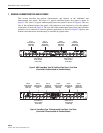
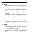
1.11 Alarm Contact Operation
Each bus contains circuitry that opens and closes a set of alarm contacts when any fuse on the
bus fails or when the input power to the bus is lost. These contacts may be used to open or close
a loop connected to an external alarm system.
The alarm circuitry provides Form C alarm relay contacts. During normal operation, the
normally open (NO) contacts remain open and the normally closed (NC) contacts remain
closed. When a fuse fails on either bus or power to either bus is lost, the NO contacts close
creating a connection between NO and common (C) and the NC contacts open creating an open
circuit between NC and common. The current rating for each set of alarm relay contacts (three
sets are provided) is 1.0 Amp maximum.
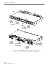
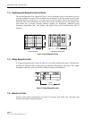
1.12 Alarm Contact Connection
Alarm contact connections are provided through three sets of wire wrap pins located on the rear
side of the fuse panel. Each set of wire wrap pins is labeled with a suggested use for monitoring
the fuse panel: audio, visual, and remote. The wire wrap pins can accept #22 to #26 AWG
copper wire.
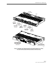
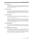
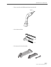
1.13 Fuse Designation Strips and Perforated Cards
Plastic designation strips with clear plastic covers are mounted above the fuse holders for each
bus. Four card sheets, each with three perforated strips, are provided with the fuse panel. The
perforated strips may be marked with the circuit designations/fuse values for each circuit/fuse
on the bus. The perforated strips are then inserted into the designation strips so that the
information on the perforated strip is positioned above the corresponding fuses. Additional
perforated strip cards and plastic covers can be ordered from ADC if required.