


ADCP-80-524 • Issue 1 • November 2001
Page 8
© 2001, ADC Telecommunications, Inc.
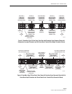
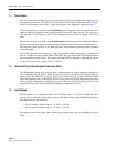
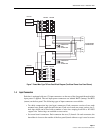
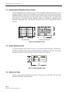
1 GENERAL CHARACTERISTICS AND FEATURES
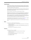
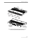
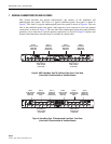
This section describes the general characteristics and features of the traditional and
uninterrupted fuse panels. The front of a typical traditional power fuse panel is shown in
Figure 3. The front of a typical uninterrupted power fuse panel is shown in Figure 4. The rear
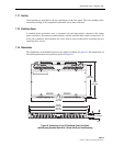
side of the traditional power fuse panel (with protective cover removed to view the optional
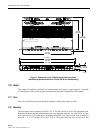
connections) is shown in Figure 5. The rear side of the uninterrupted power fuse panel (with the
protective cover removed to view the optional connections) is shown in Figure 6. Options and
features other than those described may be available by special order.
Figure 3. ADC PowerWorx Type 70 Traditional Fuse Panel, Front View
(Panel with 8 Fuses Installed on Each Bus Shown)
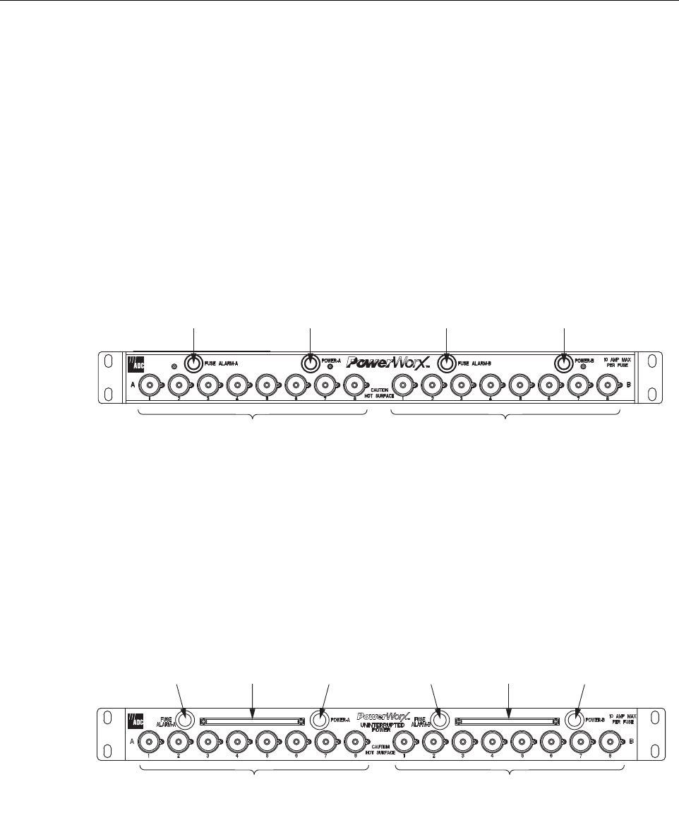
Figure 4. PowerWorx Type 70 Uninterrupted Fuse Panel, Front View
(Panel with 8 Fuses Installed on Each Bus Shown)
16151-B
BUS A
FUSE FAILURE
INDICATOR
(RED LED)
BUS A
POWER-ON
INDICATOR
(GREEN LED)
BUS B
FUSE FAILURE
INDICATOR
(RED LED)
BUS B
POWER-ON
INDICATOR
(GREEN LED)
BUS A TYPE 70
FUSE HOLDER
(8 PER BUS)
BUS B TYPE 70
FUSE HOLDER
(8 PER BUS)
16152-B
BUS A
FUSE FAILURE
INDICATOR
(RED LED)
BUS A
POWER-ON
INDICATOR
(GREEN LED)
BUS B
FUSE FAILURE
INDICATOR
(RED LED)
BUS B
POWER-ON
INDICATOR
(GREEN LED)
BUS A TYPE 70
FUSE HOLDER
(8 PER BUS)
BUS B TYPE 70
FUSE HOLDER
(8 PER BUS)
BUS B
FUSE VALUE
DESIGNATION
STRIP
BUS A
FUSE VALUE
DESIGNATION
STRIP