


ADCP-80-524 • Issue 1 • November 2001
Page 28
© 2001, ADC Telecommunications, Inc.
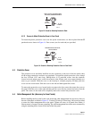
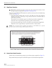
•Setscrew barrel connectors: Use only the barrel connectors on each connector assembly
that are closest to the outside of the fuse panel. Use up to #6 AWG copper wire with
insulation stripped back.
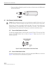
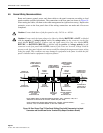
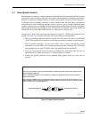
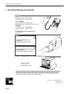
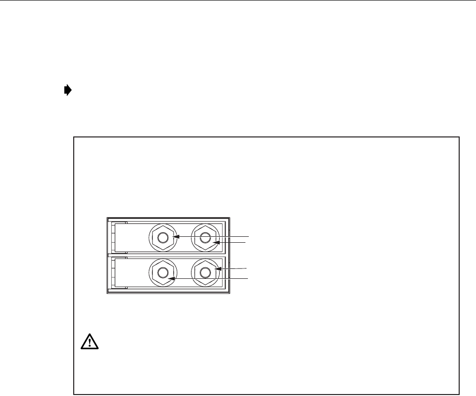
Figure 22. Input Power Connection (Compression Lug Connectors Shown)
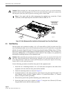
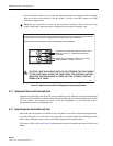
4.11 Designation Strips and Perforated Cards
Separate the perforated strips from the card and mark the strip with the circuit designation/fuse
value for each circuit/fuse on the bus. Insert the perforated strip into the designation strip, under
the clear plastic, and position the strip so that the designation on the perforated strip is
positioned above the corresponding fuse
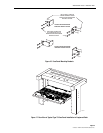
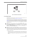
4.12 Fuse Designation Card Holder and Card
Attach the fuse designation card holder to the fuse panel, to one of the panel mounting brackets,
to a part of the rack, or at a location close to the panel, as desired. Remove the backing from the
back of the card holder and press the card holder against the mounting surface.
Fill out one of the cards (see Figure 8) with required circuit information and insert it in the card
holder.
Note: Do not loosen the set screws in the two barrel connectors that are closest to the
center of the panel. Accessing these connectors may render the warranty void.
CONNECT INPUT VOLTAGE WIRE LABELED "BATTERY," "BATT,"
"NEGATIVE," "NEG," OR "-" AND/OR THE VOLTAGE VALUE
("HOT" WIRE)
CONNECT INPUT RETURN WIRE LABELED "RTN," "RETURN,"
"BATTERY GROUND," "POSITIVE," "POS." OR "+."
USE THE INCLUDED 2-HOLE LUGS WITH #2 AWG COPPER WIRE WITH INSULATION STRIPPED BACK OR USE APPROPRIATE
OPTIONAL 2-HOLE LUGS AVAILABLE AS ACCESSORIES WITH APPROPRIATE SIZE AWG COPPER WIRE.
TORQUE THE NUTS TO APPROXIMATELY 16 POUND-FORCE INCHES (1.8 NEWTON METERS).
16163-C
CAUTION: CARE SHOULD BE TAKEN TO NOT REVERSE THE INPUT WIRES
TO THE FUSE PANEL. WITHIN THE FUSE PANEL, THE INTERNAL BATTERY
(NEGATIVE VOLTAGE) WIRING IS FUSED, BUT THE INTERNAL RETURN
WIRING IS NOT FUSED.