


ADCP-90-216
Issue 2, January 1998
Page 12
1998, ADC Telecommunications, Inc.
D. Fiber Storage
5.11
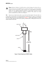
Open the rear door about 2 inches (5 cm) and lift it from its hinges. Place the cover
where it will not be scratched or damaged.
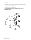
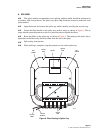
5.12
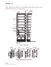
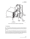
Route OSP/IFC fibers through a side access opening in the chassis to the assigned
drawer of the splice module. Service loop should be stored in the assigned drawer per Figure 8.
Make sure to route fibers through the retaining ring in the back of the drawer. Passing the fibers
through the retaining ring is required for the first pass only. The fiber bundles (service loop)
should make three and one-half passes around the radius limiters and then be routed such that the
end of the braided sleeve or protective sleeve occurs at a point between the two side radius
limiters, noted as position “A” in Figure 8, and just onto the splice tray. Coil the fiber bundles
around the four radius limiters, either counter-clockwise if entering the splice drawer from the
right, or clockwise if entering the splice drawer from the left.
E. Pigtails
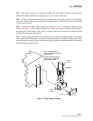
5.13
Individual fibers with a factory installed connector on one end should be bundled together
in groups (usually 12) and protected by a braided sleeve or loose tubing, and routed from the FDS
connector module to the splice module splice drawer through fiber pass-through holes at the top or
bottom of the module, depending on the location of the FDS connector module.
5.14
Because the pigtails and IFC/OSP fiber bundles must form a single service loop to enter the
splice tray, both bundles must enter the splice module from the same side (either left or right side).
OSP CABLE AT
LEFT SIDE
RETAINER
CLIPS
RADIUS
LIMITER
FIBERS
4132-A
AA
Figure 8. Fiber Routing in Splice Module