


ADCP-90-216
Issue 2, January 1998
Page 9
1998, ADC Telecommunications, Inc.
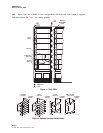
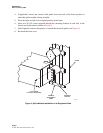
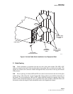
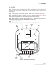
#12-24 SCREW
(2 PLACES EACH SIDE)
INTERBAY
MANAGEMENT
PANEL
1217-A
VERTICAL CABLE
GUIDE MOUNTING
HOLES
VERTICAL CABLE
GUIDE MOUNTING
HOLES
VERTICAL
CABLE GUIDE
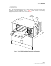
Figure 5. Vertical Cable Guide Installation in an Equipment Rack
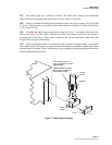
C. Cable Routing
5.04
Cable installation is performed from the rear side of the splice module. The OSP or IFC
cables are routed to the back of the module chassis from either above or below the module. The
pigtails are routed to the connector module through the fiber access holes in the top and bottom
of the chassis.
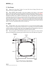
5.05
Prior to splicing, all cables (OSP and IFC) are routed to and secured to the side of the splice
module using a cable clamp kit. A total of eight cable clamp positions are available at both sides of
the chassis. To avoid congestion, OSP and IFC cables should be installed on opposite sides of the
module. Cables should be clamped as close as possible to the splice module to which the fibers will
be routed to reduce the length of cable sheath that needs to be stripped and cleaned.