


ADCP-90-216
Issue 2, January 1998
Page 6
1998, ADC Telecommunications, Inc.
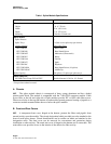
Table 1. Splice Module Specifications
FEATURE SPECIFICATION
Dimensions
Height 7 in. (17.78 cm)
Width 17 in. (43.18 cm)
Depth 11 in. (27.94 cm)
Mounting 19-inch or 23-inch rack
Splice Details
Splice Drawers 6
Splice Trays 12 (One or two splice trays per drawer)
Catalog Number: Splice Chip Type:
FST-F3DF-FT Bare Fusion
FST-F3DF-HS Heat Shrink Fusion
FST-F3DF-MT Mechanical (Elastomeric)
FST-F3DF-RT Rotary
FST-F3DF-3M FibrLok
FST-F3DF-NT Qpak
FST-F3DF-RC Raychem
FST-F3DF-HS18 Heat Shrink Fusion (18 splices)
FST-F3DF-HSAC AOFR Clip
Splice Capacity 144 splices (12 splices per splice tray)*
Cable Clamp Kits
IFC/OSP Cable Clamp FL2-ACC007 Outside diameter 0.5-0.8 in. (13-20 mm)
* Except where otherwise noted.
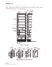
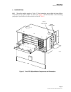
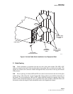
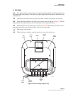
A. Chassis
4.02
The splice module chassis is constructed of heavy gauge aluminum and has a baked
powder paint finish. The module is compatible with the 7-inch FDS connector module. Cable
access holes at the left and right side of both modules provide IFC or OSP cable fiber access.
Fiber access holes in the top and bottom of both modules permit protected routing of pigtails to a
connector module mounted either above or below the splice module.
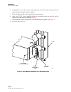
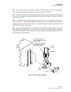
B. Front and Rear Covers
4.03
A transparent front cover, hinged at the bottom, protects the fibers and pigtails from
normal activity near the module. The circuit designation labels provided are to be attached to the
front of each splice drawer. Circuit identification can be written on labels and attached to the
designation cards. The front cover can be removed for convenience and protection during
installation or other activity. The metal rear cover is hinged at the bottom and is removable. The
removable cover provides access to the interior of the chassis for fiber activity.