


ADCP-90-216
Issue 2, January 1998
Page 8
1998, ADC Telecommunications, Inc.
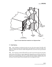
4. If applicable, remove the vertical cable guide from each side of the frame position in
which the splice module is being installed.
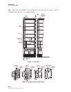
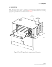
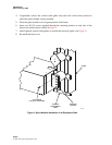
5. Place the splice module in its assigned position in the frame.
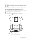
6. Insert two #12-24 screws supplied through the mounting bracket at each side of the
chassis and in the frame as shown in Figure 4.
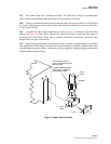
7. Install optional vertical cable guides or reinstall the removed guides (see Figure 5).
8. Re-attach the front cover.
1216-A
FRAME
INTERBAY
MANAGEMENT
PANEL
MOUNTING
BRACKET
#12-24 SCREW
(2 PLACES - BOTH SIDES)
Figure 4. Splice Module Installation in an Equipment Rack