


14
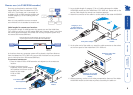
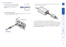
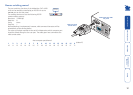
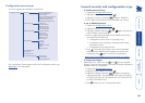
3 Connect the other end of the cascade
link cable to the remote user RJ45
socket on the front panel of the
lower unit.
4 Repeat steps 2 and 3 for the cascade
links between each AdderView
CATx 1000 unit.
Once the AdderView CATx 1000
units and computers have been
connected, you can edit their
names to make it much
easier to locate them.
See the To create/
edit computer
names section in
the Configuration
chapter for more details.
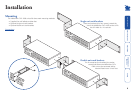
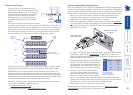
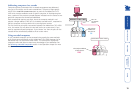
Connecting units in cascade
The method for cascading AdderView CATx 1000 units is straightforward and
requires no hardware settings or lengthy configuration process.
The method of linking AdderView CATx 1000 units is the same regardless of the
cascade level, or number of devices attached. Put simply:
• A single cascade link is made by connecting a computer connections
socket of one unit to the remote user port socket of the unit below
it.
Please consider the following when making cascade connections between
AdderView CATx 1000 units.
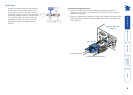
Tips for successful cascading
• The maximum number of levels for a cascade is two.
• For each cascade link, use a standard category 5, 5e or 6 twisted-pair cable,
terminated at each end with an RJ45 connector. There must be no crossover
connections within the cable. The cascade link cables can be up to 50m (160
feet) in length. However, remember that the overall length between the
remote user (via an X100 or X200 extender) and any computer (via a CAM)
must not exceed 300m (980 feet) - that figure includes the cascade link
cables. Also ensure that the total length from the top AdderView CATx 1000
to any CAM does not exceed 10m.
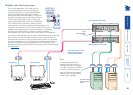
• The procedure given opposite may be carried out in any order but for clarity
the instruction will begin at the higher level AdderView CATx 1000 unit
(here called the upper unit), i.e. the one that is being fed into by a unit at
the cascade level below (here called the lower unit). The procedure remains
the same regardless of exactly which cascade levels are being connected.
The basic rule is that each link is made by connecting a COMPUTER
CONNECTIONS port of the upper switch to a CATx USER PORTS of the lower
switch.
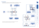
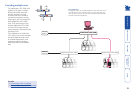
See also
• Addressing computers in a cascade
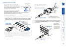
To connect units in cascade
1 Ensure that power is disconnected from the
AdderView CATx 1000 and all other units to
be connected.
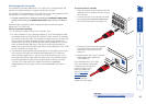
2 Connect one end of the cascade link cable
to an appropriate COMPUTER CONNECTIONS
port on the rear panel of the upper unit.
INDOOR
USE
ONL
Y
3 2
1
7
6
5
COMPUTER
CONNECTIONS
K
V
M
o
n
l
y