


4
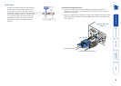
AdderView CATx 1000 features - front and rear
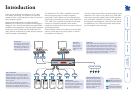
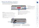
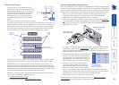
The AdderView CATx 1000 units pack a great deal of functionality into a
compact space. Both models occupy half of a single 1U rack space and provide
most of their connectors at the rear face. The smart front face features the
remote user link port and the operation indicators.
INDOOR
USE
ONL
Y
5V
2.0A
412 311 210 19
816 715
614
513
OPTIONS
COMPUTERCONNECTIONSCOMPUTERCONNECTIONS
LOC REM OSD UPG LCK PWR
www.adder.com
KVM
only
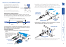
Options port
This RS232 serial port can separately support the following functions:
• Power switching - can be configured to control multiple power switching devices.
• Remote control switching - commands can be received that will change the
channel, as necessary.
• Synchronisation - allows the actions of two or more AdderView CATx 1000
switches to be synchronised so that multiple computers/video screens can be
switched and accessed.
• Upgrades - used to update the internal firmware when necessary by connecting to
a computer.
• Transferring configuration settings - allows information about the connected
computers to be saved and restored.
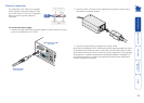
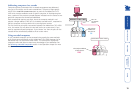
Local user port
Connect a USB keyboard and mouse, plus a video
monitor and optional speakers to these connectors.
These allow you to perform the initial configuration
of the AdderView CATx 1000. Additionally, you
can use these to locally control the connected
computer(s).
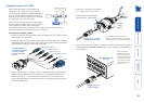
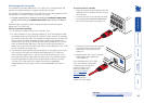
Computer ports
Each computer connects to one of these ports
via standard category 5, 5e or 6 cabling. At the
other end of the cabling a CAM (Computer Access
Module) is used to provide the necessary keyboard,
video, mouse and optional speaker connections.
Power input
The power supply
connects here.
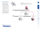
Remote user port
This port can either be used to connect a single
remote user (with an optional X100 or X200
extender module) at a distance of up to 300m
or used to connect other AdderView CATx
1000 units in cascade.
IMPORTANT: This is not an Ethernet port and
must not be connected to any network.
Indicators
These six indicators clearly show the key aspects of operation:
• LOC Keyboard or mouse data are being received from the local console.
• REM Keyboard or mouse data are being received from the remote console.
• OSD Indicates that the on screen display is currently active.
• UPG Indicates that the unit is currently in upgrade mode.
• LCK Security mode enabled and no user logged in.
• PWR Power input indicator.