


12
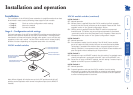
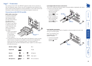
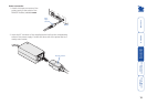
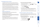
Serial cable connections
You can attach multiple serial
devices (such as touch screen
inputs) to the remote module (up
to two on the MS2 model or up to
four on MS4 model).
Note: The links support software
or hardware handshaking up to a
maximum baud rate of 56Kb/s.
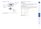
For each required serial
connection:
1 Connect the cable from the
serial device to one of the
9 pin ports on the LOCAL
module (labelled SERIAL 1 to
SERIAL 4).
2 Ensure that the corresponding
serial connection at the
LOCAL module matches this
device and the necessary port
on the host system.
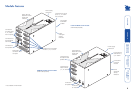
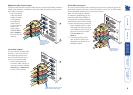
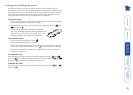
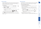
Video outputs
You can connect multiple video monitors to the REMOTE module (up to two on
the MS2 model or up to four on the MS4 model).
1 Attach the signal
leads from each
video monitor to
the output sockets
(labelled VIDEO OUT
1 to VIDEO OUT 4) on
the REMOTE module.
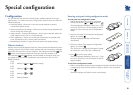
VIDEO OUT
4
VIDEO OUT
3
VIDEO OUT
2
VIDEO OUT
1
REMOTE
Connections from
monitors (two
outputs available
on MS2 model)
SERIAL
4
SERIAL
3
SERIAL
2
SERIAL
1
POWER
TO
4
LOCAL
TO
3
LOCAL
TO LOCAL
2
TO LOCAL
1
INDOOR
USE ONL
Y
REMOTE
twisted pair
connections -
cables must be
of equal lengths
SERIAL
4
SERIAL
3
SERIAL
2
SERIAL
1
PO
WER
TO
4
LOCAL
TO
3
LOCAL
TO LOCAL
2
TO LOCAL
1
INDOOR
USE ONL
Y
REMOTE
Connections to serial devices
(two outputs available on
MS2 model)
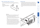
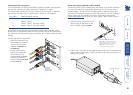
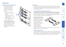
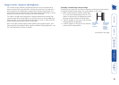
Twisted pair link connections
The links between the LOCAL and REMOTE modules are made using between
one and four twisted pair cables, specied to Category 5 or higher.
The various cable connections carry the following channel signals (if particular
channels are not used, then corresponding link cables are not required):
Link cable Channel signals carried
1 Keyboard, Mouse, Audio, Video 1, Serial 1
2 Video 2, Serial 2
3 Video 3, Serial 3 (not MS2 model)
4 Video 4, Serial 4 (not MS2 model)
IMPORTANT: Ensure that the total twisted pair cable length (including patch
boxes) does not exceed 200 metres for any link cable. Ensure that the multiple
link cables are all of the same length to avoid the risk of uneven delays on video
images.
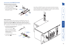
For each required link connection:
1 Insert the connector
from the twisted pair
cable link into one of
the sockets (labelled TO
LOCAL 1 to TO LOCAL 4).
2 Ensure that the other
end of the twisted
pair link connects to
the corresponding
numbered socket on the
LOCAL module (labelled
TO REMOTE 1 to TO
REMOTE 4).