


Chapter 7. Creating a Dial Plan
7-2
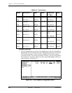
ATLAS 800
PLUS
User Manual 61200226L1-1
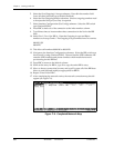
One ATLAS 800
PLUS
(A) operates as the network while the other (B) “termi-
nates” the network. In the example in Figure 7-2, ATLAS A is emulating the net-
work and the PRI interface is a User Termination, while the PRI interface of
ATLAS B is a Network Termination.
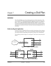
Understanding the Dial Plan
The Dial Plan menus are subdivided into three separate menus. These include
menus to enter the numbering plan for Network Terminations and User Termina-
tions, and a menu to set global parameters.
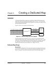
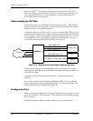
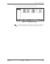
A corporate office has T1 RBS service for voice, but wants to add a PRI for video
conferencing and remote access. They would like to use the PRI for all functions
but still want to use the incoming BRI to supply added bandwidth. They want to
provide BRI lines to the video equipment, provide a PRI to the remote access
server (RAS) and send an RBS T1 to the PBX. (see Figure 7-3).
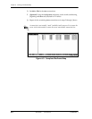
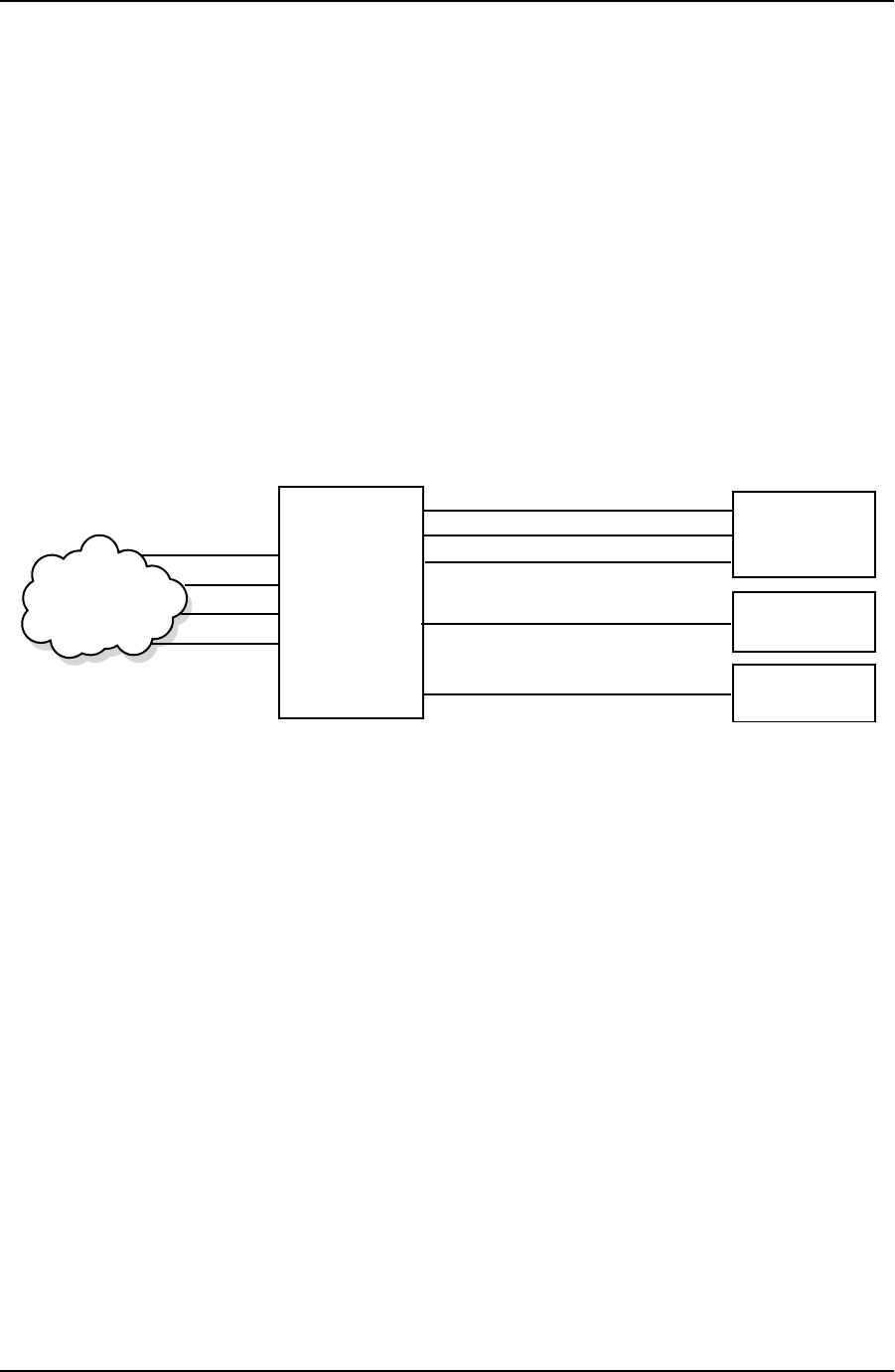
Figure 7-3. Remote Access and Video Conferencing Setup
For this example, the User Termination BRI lines (D, E, F) each have a specific
phone number. The PRI serving the RAS has an 8 number hunt group, and the T1
to the PBX uses DID.
Assume that all calls originating from the PBX to 1-900 numbers are to be
restricted.
Also assume that the Network Termination BRI lines (BRI A, B, C) should only
allow outgoing calls to other local corporate offices for Video conferencing. The
numbers fall in the range of 888-0100 to 888-0120
Configure the Ports
Follow the steps described in the “Creating a Dedicated Map” on page 6-1 to con-
figure the Controller T1/PRI interfaces. This configuration action only brings up
the T1 transport.
The BRI configuration (SPID and phone number) is part of the Dial Plan.
ATLAS 800
PLUS
Video Conf.
PBX
RAS
BRI-D (888-1001)
T1-A (RBS 821-8XXX [x24] x DID)
PRI -B (888-1010 x 8)
BRI-E (888-1002)
BRI-F (888-1003)
Network