


361221051L1-5, Issue 161221051L1-5A
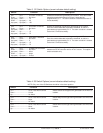
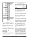
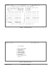
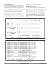
Table 2. S1 Switch Options (arrow indicates default setting)
Switch Function
S1-1.................................. Errored Seconds
Down ................................ Minor Alarm
Up (open) ......................... Major Alarm
S1-2.................................. Severely Errored Seconds
Down ................................ Minor Alarm
Up (open) ......................... Major Alarm
S1-3.................................. Unavailable Seconds
Down ................................ Major Alarm
Up (open) ......................... Critical Alarm
S1-4........... S1-5 ............. HFAC Fuse Alarm Type
Down ......... Down............ No Alarm
Up (open) .. Down ............ Minor Alarm
Down ......... Up (open) ..... Major Alarm
Up (open) .. Up (open) ..... Critical Alarm
S1-6........... S1-7 ............. HTU-C Fuse alarm Type
Down ......... Down............ No Alarm
Up (open) .. Down ............ 1 or more: Critical
Down ......... Up ................ 1: Major, 2-13: Critical
Up (open) .. Up (open) ..... 1-5: Major, 6-13: Critical
S1-8.................................. HCOT-CTL Fuse Alarm Type
Down ................................ Major Alarm
Up (open) ......................... Critical Alarm
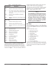
Description
Selects the type of alarm generated when the errored seconds
(ES) counter exceeds the programmed threshold (see Table 2,
S2-1, S2-2).
Selects the type of alarm generated when the severely errored
seconds (SES) counter exceeds the programmed threshold (see
Table 2, SW2-3, SW2-4).
Selects the type of alarm generated when the unavailable
seconds (UAS) counter exceeds the programmed threshold (see
Table 2, SW2-5, SW2-6).
Selects the type of alarm generated in response to an HFAC fuse
failure. Switch SW3 must also be set correctly for this alarm to
function properly (see Table 3). This option is hardware-
selectable only.
Selects the type of alarm generated in response to a specific
number of HTU-C fuse failures.
Selects the type of alarm generated in response to an HCOT-CTL
system controller fuse failure. This option can only be selected
by switch.
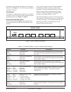
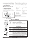
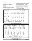
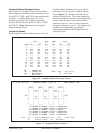
SW3
Up
REAR VIEW
Figure 3. SW3 Location and Options
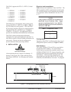
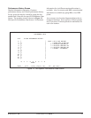
the address, select the desired address in the Options
Setup Screen (Figure 11), or set the rotary switches as
indicated in Figure 2.
Unit Options
Two banks of configuration switches (S1, S2 and S3,
see Figure 2 and 3) are used to select advanced alarm
reporting features (see Tables 2, 3 and 4).
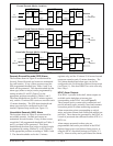
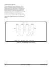
Errored Seconds (ES) Alarm
The locations shown in Figure 4 are monitored for
errored seconds and counts are maintained for each
location.
If any of these counts exceed the ES programmed
threshold (see Tables 1 and 2) an alarm will be
generated. This alarm threshold and the alarm type
(minor or major) can be programmed by setting
switches S1 and S2 (Figure 2) to the appropriate
positions, according to Tables 1 and 2.
The alarm thresholds are for the 15-minute registers
only, and the 15-minute ES counts are zeroed at each
15-minute boundary. The ES alarm threshold and
alarm type can also be configured in the Craft
interface Options Setup screen.