


6
61221051L1-5, Issue 1 61221051L1-5A
resulting from blown fuses in the HFAC, HTU-C, or
HCOT units, or from communications failure between
any HTU-C and the HFAC. Alarm severity and
threshold value can be provisioned for the errored
second, severely errored second, and unavailable
second parameters.
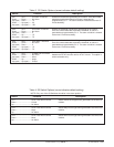
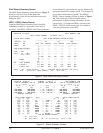
An option available on the HFAC Option Setup screen
allows external DSX-1 or DS1 alarms to be enabled or
disabled. This option can only be changed in the
HFAC menu (no dip switch option) and the factory
default is disabled (see Table 5).
HFAC Fuse Alarm
An alarm may be generated as a result of an HFAC
fuse failure. For alarm processing to work, two sets of
switches (S1 and S3) must be programmed. See Table
1 and 4. Both switches must be set properly for the
HFAC fuse alarm to operate correctly.
HTU-C Fuse Alarm
An alarm may be generated as a result of an HTU-C
fuse failure. The HFAC controller will sense the
failure and process this alarm event according to
switch settings as defined in Table 2.
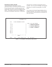
3. CONNECTIONS
The HFAC plugs into Slot 0 (labeled HFAC) of the
ADTRAN E220 shelf. Push firmly to ensure the card
seats properly. Connections to the HFAC are made by
wire wrap connections to the backplane-mounted
connector. JP1 is the primary interface connector for
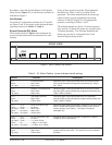
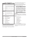
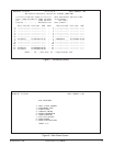
the HFAC. Figure 5 shows the wire-wrap connector
terminal pin assignments.
Alarms
A set of alarm contacts is provided through backplane
wire-wrap connections (Figure 5). Wiring can be
made to the appropriate pins on JP1 for normally open
or normally closed connections for alarm conditions.
Connection is made to the Common (C) pin and to the
Normally Open (NO) or Normally Closed (NC) pin.
Visible and audible alarm contact connections are
provided for critical, major, and minor alarms. An
audible alarm cutoff function can be initiated by
pressing the ACO push-button on the HFAC, or by
providing closure between the Remote ACO pins on
the JP1 connector. The backplane is labeled with
appropriate markings for the alarm and alarm cutoff
connections.
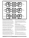
System Communications
If the HFAC is to be used as part of a larger system
under the control of an ADTRAN E220 HCOT-CTL
system controller, then shelf-to-shelf connections are
required. Two RJ45S jacks, JP6 and JP7, located on
the shelf backplane, provide shelf-to-shelf
communications. A 4- or 8-wire cable with RJ45S
type jacks should be used to supply these
interconnections. The sequence of connections should
be from the RS422 OUT port of the shelf containing
the E220 HCOT-CTL system controller to the RS422
IN port of the next shelf. Follow this procedure to
Fault
Locate
1
2
3
4
5
6
7
8
9
10
11
12
13
14
15
16
17
18
19
20
21
22
23
24
25
T
R
HFAC SLOT
(JP1)
Critical
26
27
28
29
30
31
32
33
34
35
36
37
38
39
40
41
42
43
44
45
46
47
48
49
50
VIS NO
VIS C
VIS NC
AUD NO
AUD C
AUD NC
Major
VIS NO
VIS C
VIS NC
AUD NO
AUD C
AUD NC
Minor
VIS NO
VIS C
VIS NC
AUD NO
AUD C
AUD NC
Remote
ACO
NO: Normallly Open Position
NC: Normally Closed Position
C: Common
Figure 5. HFAC Wire-Wrap Pin-Out Design
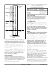
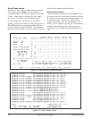
Options Screen
Menu Item No. Function Description
Table 5. External HTU-C/HTU-R Alarm Options
(Software-Selectable Only)
(arrow indicates default setting)
5 ...........................EXT HTU-C/R Alarms Disables and
enables the alarms
resulting from external
DSX-1 or DS1
Disabled
Enabled