


761221051L1-5, Issue 161221051L1-5A
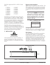
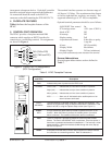
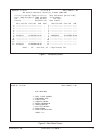
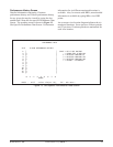
Figure 6. Control Port Pin Assignments
(DCE Configuration)
6
7
8
9
1
2
3
4
5
TXD (TXD to DTE)
RXD (TXD from DTE)
DTR
SGN GND
DSR
RTS
CTS
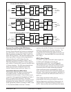
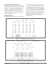
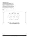
interconnect subsequent shelves. Each shelf controller
should be assigned unique sequential shelf addresses.
No connection should be made to the RS422 in
connector on the shelf containing the E220 HCOT-CTL.
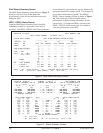
4. FACEPLATE FEATURES
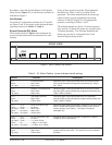
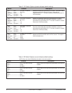
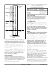
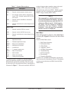
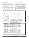
Table 6 defines the faceplate features of the
HFAC.
5. CONTROL PORT OPERATION
The HFAC provides a faceplate-mounted DB9
connector which supplies an RS232 interface for
connecting to a controlling terminal. Pin assignments
are shown in Figure 6.
The terminal interface operates at a data rate range of
4.8 kbps to 19.2 kbps. The asynchronous data format
is fixed at eight data bits, no parity, one stop bit. The
supported terminal type is VT 100, or compatible.
Optional terminal parameters should be set as follows:
•XON/XOFF flow control On
•TX carriage return <CR> (not <CRLF>)
•Send ACK* Off
•Linewrap Off
•Duplex setting Full
•Asynchronous format 8 data bits, no parity,
1 stop bit
•Cursor Off (if possible)
•Display Width 80 columns
•Display Height 24 lines (minimum)
*
or any other autonomously-sent character from terminal
Screen Abbreviations
Screen diagram abbreviations used are defined in
Table 7.
Table 6. HFAC Faceplate Features
Indicators
and LEDs
PWR
ALARMS
SHELF
ADDRESS
Button
ACO
Fuse
RS232
Description
Indicates that power is present to the HFAC card.
Critical (red)...... Indicates that a critical alarm condition is present.
Major (red)........ Indicates that a major alarm condition is present.
Minor (yellow)... Indicates that a minor alarm condition is present.
ACO ................. Alarm cut off. Indicates that the audible portion of an
alarm has been terminated.
The shelf address is indicated using two 7-segment LED displays. The
address is programmed using the switches described in subsection 2 and
tables A and B; or using the Options Setup screen (see Figure 11).
A single momentary push-button provided to operate the alarm cut off
function. When the button is present, the audible portion of an active
alarm is silenced. The condition of the alarm itself is not affected.
This 0.25 -amp fuse is provided to protect the card from power-related
failures. The fuse is a BUSS BMT-0.25, or equivalent. If the fuse opens, a
fuse alarm is generated as described in subsection 2. The fuse has a visual
tripped indicators. When the metal tab (visible through the cover) flips up,
the fuse has opened.
A faceplate-mounted DB9 connector which supplies an RS232 interface
for connection to a controlling terminal. Refer to subsection 5.
PWR
R
S
2
3
2
HFAC
1221051L1
CRAFT INTERFACE
0.25 AMP
SHELF ADDRESS
A
L
A
R
M
S
CRITICAL
MAJOR
MINOR
ACO