


Table of Contents
Step 3. Select the number of DS0s/Port:_____12___ ...........................87
Step 4. Complete the DS0 Map Configuration .....................................88
Step 5. Complete a Configuration Table for the DSX-1
PBX Passthru ...........................................................................89
Step 6. Activate Configuration Menu ....................................................89
Configuring the Network Interface ...............................................................90
Configuring the DS0 Map ...............................................................................92
Temporary Map ................................................................................................95
Review.........................................................................................................95
Edit...............................................................................................................96
Configuring the Ports ...............................................................................98
Testing Example ..............................................................................................100
Far End Looped Back Test .....................................................................100
Network Interface Test ....................................................................100
Test Termination ........................................................................105
Appendix A. TSU 600 Menu Tree ..............................................................107
Appendix B. DTE Data Rate Chart............................................................109
Appendix C. System Configuration Chart .............................................. 111
Step 1: Configure Network ...................................................................111
Step 2: Configure DTE PORT: (1.1Nx56/64) .....................................111
Step 3: Select number of DS0s/PORT __________________ ...........112
Step 4: DS0 Map A Configuration........................................................113
Step 5: DS0 Map B Configuration ........................................................113
Figures
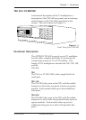
Figure 1-1. Front View of the TSU 600 ...........................................................3
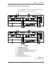
Figure 1-2. TSU 600 Rear Panel .......................................................................5
Figure 1-3. TSU 600 Interfaces.........................................................................7
Figure 1-4. TSU 600 Option Slot Arrangement ...........................................11
Figure 1-5. Network Timed Clock Source ...................................................13
Figure 1-6. DTE Clock Source .......................................................................14
Figure 1-7. Internal Clock Source .................................................................15
Figure 1-8. Normal (CSU) ..............................................................................16
Figure 1-9. Network Loopback Tests ...........................................................18
Figure 1-10. DTE Interface Loopback.............................................................19
Figure 1-11. Port Interface Loopback .............................................................19
Figure 1-12. TSU 600 Option Modules...........................................................21
Figure 1-13. Bridge, PBX, Video Conferencing Application Set Up ..........21
Figure 1-14. All Voice Application Set Up .....................................................22
vi TSU 600 User Manual 61200.076L2-1