


Chapter 3. Operation
61200.076L2-1 TSU 600 User Manual 47
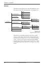
MENU STRUCTURE
The TSU 600 uses a form of hierarchical menus to
access all features. The topmost or Main menu level
(see Figure 3-6) leads to submenus which are grouped
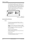
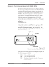
by functionality. All menu operations are displayed in
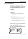
the LCD window as illustrated in Figure 3-7.
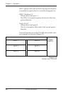
The menu structure diagram, shown in Figure 3-6, is a
limited overview. A detailed description of each menu item,
presented in menu order, immediately follows. A complete
menu diagram is shown in the appendix, TSU 600 Menu
Tree.
MAIN MENU
1)STATUS
1)NETWORK (NI)
2)UNIT
3)MAP EXCHANGE
4)MAP IN USE:A (B)
5)DS0 MAP A
6)DS0 MAP B
7)PORT CONFIG
2)CONFIG
3)UTIL
1)NI PERF REPTS
2)NI ERRORS
3)ACTIVE ALARMS
4)VIEW HISTORY
5)PORT STATUS
6)REMOTE PORT
1)TIME/DATE
2)FACTORY RESTORE
3)SET PASSCODE
4)UNIT ID
5)SOFTWARE REV
6)PORT UTILITY
1)NETWORK TESTS
2)RUN SELFTEST
3)PORT TEST
4)CANCEL TESTS
4)TEST
Figure 3-6
The Four Opening Menus
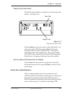
Menu flow is normally depicted from left to right.
Arrows on the lower right of the screen indicate the
direction of scrolling to use to view additional menu
items. At every level of the menu pressing Cancel
returns the system to the previous menu level. Press-
ing Cancel repeatedly returns the system to the Main
menu.