


Chapter 3. Operation
40 TSU 600 User Manual 61200.076L2-1
OK• 1MODULE TEST
TSU 600
ALARM
OK• 2 TEST ALARM
OK• 3 TEST ALARM
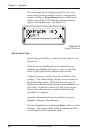
ALARMERRORTEST
COPY HOME SHIFT
OKREMOTE
ABC
REMOTE ALARM CLEAR
DEF
0#
123
789
456
CANCEL
ENTER
OK• 5 TEST ALARM
OK• 4 TEST ALARM
OK• 6 TEST ALARM
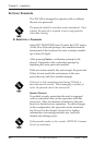
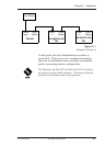
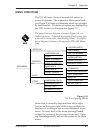
1. REMOTE
2. LCD Window
3. CSU Status
4. Key Pad
5. Module Status
6. CANCEL
7. Up and Down Arrow Keys
91113
1
32
7101214
6
8
45
8. ENTER
9. COPY
10. REMOTE
11. HOME
12. ALARM
13. SHIFT
14. CLEAR
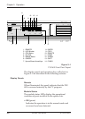
Figure 3-1
TSU 600 Front Panel Layout
The display panels and operation keys called out in
Figure 3-1 are described in the following sections:
Display Panels
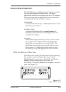
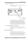
Remote
When illuminated, this panel indicates that the TSU
600 is accessed remotely by the PC program.
Module Status
The module status LEDs display the operational
condition of ports installed in the option slots.
• OK (green)
Indicates the operation is in the normal mode and
no errors have been detected.