


MIC-3368 Series User Manual -- Page
6
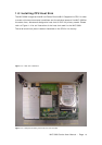
1.4 Jumpers
1.4.1 Jumper Locations
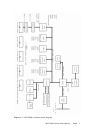
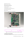
The MIC-3368 provides a jumper (JP2) for configuring your board for specific
applications other than the default settings. Table 1-1 lists the jumper function.
Figure 1-2 illustrates the jumper location. Read this section carefully before
changing the jump setting on your MIC-3368 card.
Table 1-1: MIC-3368 jumper descriptions
Number Function
JP1 Clear CMOS
JP2 CF Mode (CF Master / Slave)
JP3 Hot-swap connector (For MIC-3368C only)
JP6 Primary PCI VIO
JP7 Secondary PCI VIO
JP8 PMC Module voltage
1.4.2 Jumper Settings
This section tells how to set the jumpers to configure your card. It gives the card
default configuration and your options for each jumper. After you set the jumpers
and install the card, you will also need to run the BIOS Setup program (discussed in
Chapter 6) to configure the serial port addresses, floppy/hard disk drive types and
system operating parameters. Connections, such as hard disk cables, appear in
Chapter 2. For the locations of each jumper, see the board layout diagram depicted
earlier in this chapter.
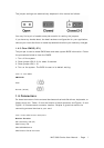
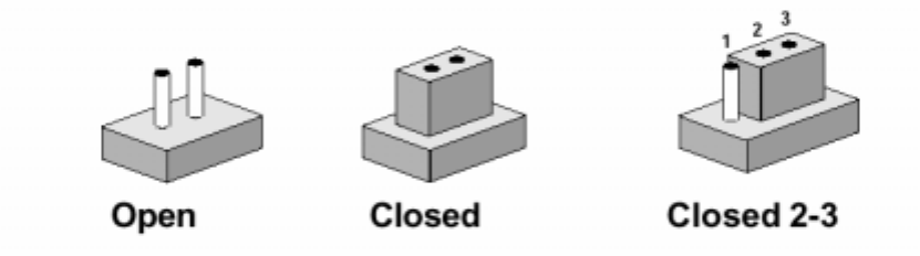
You configure your card to match the needs of your application by setting jumpers.
A jumper is the simplest kind of electric switch. It consists of two metal pins and a
small metal cap (often protected by a plastic cover) that slides over the pins to
connect them. To "close" a jumper you connect the pins with the cap. To "open" a
jumper you remove the cap. Sometimes a jumper will have three pins, labeled 1, 2
and 3. In this case you connect either pins 1 and 2 or 2 and 3.