


MIC-3368 Series User Manual -- Page
VII
Figures
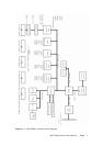
Figure 1-1: MIC-3368 functional block diagram ........................................... 7
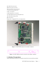
Figure 1-2: MIC-3368 jumper and connector locations .................................. 11
Figure 1-3: MIC-3368 front panel connector and indicator locations …………………..12
Figure 1-4: Heat sink installation .............................................................. 15
Figure 5-1: Setup program initial screen .................................................... 46
Figure 5-2: CMOS setup screen ................................................................ 47
Figure 5-3: BIOS features setup screen...................................................... 48
Figure 5-4: CHIPSET features setup screen ................................................ 52
Figure 5-5: Power management setup screen ............................................. 53
Figure 5-6: PCI configuration screen ......................................................... 54
Figure 5-7: Integrated peripherals ............................................................ 55