


31
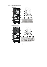
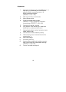
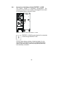
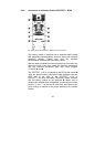
♦ Mount the connection cover of the cable clamping unit.
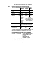
5.2.2 Connection Cross-Sections and Fuse Protection
The required dimensions can be found in the following table:
PROTECT
1.100
PROTECT
1.150
*
PROTECT
1.200 *
Max. current consumption
(bypass)
46A 68A 91A
Incoming mains cable
(UPS input)
min.
max.
10 mm²
16 mm²
16 mm²
35 mm²
25 mm²
35 mm²
Load connection
(UPS output)
min.
max.
10 mm²
16 mm²
16 mm²
35 mm²
25 mm²
35 mm²
Battery connection Via
enclosed
battery
connection
cable
protected
against
polarity
reversal
Min. 16 mm², Max. 35 mm²
per terminal
Battery connection cable is
included with the battery unit
Observe earth-fault- and
short-circuit-proof routing!
Mains fuse (UPS input) 50A gl 80A gl 100A gl
When using line safety switches, observe
trigger characteristic: “D”
Line safety switch “B” characteristic Load fuse
(recommended max.)
16A 20A 25A
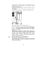
* To ensure a reliable strain relief, individual wires must be laid
especially for connecting the 15 and 20 kVA UPS systems.
Recommended connection cable acc. to VDE 0298-4:
Specially for 15 and 20 kVA:
Special rubber-insulated wire
NSGAÖU or NSGAFÖU
or NYY or
Radox 4GKW-AX
e.g. Huber & Suhner
Alternatively, the 10 kVA UPS system can also be connected
via a multi-wire rubber-sheathed cable.