


34
5.3.4 Connection of the Loads
In order to ensure the safety of personnel during installation work,
make sure that the connections are made under the following
conditions:
♦ No mains voltage present.
♦ The loads are switched off.
♦ UPS is switched off (display completely blank).
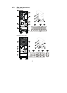
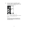
To disconnect the PROTECT 1., carry out the following steps:
♦ Place the “maintenance switch” manual bypass on
the back of the UPS in the “bypass” position. For
this purpose, first remove the 4 screws of the cover
(no.
3, p. 27/28).
♦ Put the mains input miniature circuit breaker (no.
2, p.
27/28) to the “OFF” position.
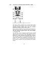
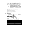
Connect the loads as follows (terminals 1.3, p. 27/28):
Connect the UPS terminals /
PE = ground, N = neutral
conductor, L = phase that are marked with “OUTPUT” with the
corresponding terminals of your UPS subdistribution.
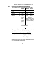
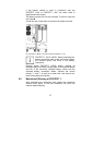
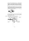
5.4 Connection of External Battery Modules
The PROTECT 1. requires the use of at least one external
battery module. Two preconfigured battery cubicle types are
available. Both versions guarantee an increase in the attainable
standby time due to their parallel connection capability (see
also chapter 2.3).
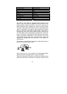
PROTECT 1.100 PROTECT 1.150 PROTECT 1.200
PROTECT
1.100 BP
- -
PROTECT
1.BP20
The two cubicle types are distinguished in the following. Follow
5.4.1 if you use the PROTECT 1.100 BP or 5.4.2 when using
the PROTECT 1.BP20.
No
mix !