


33
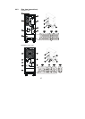
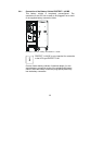
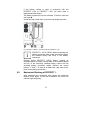
♦ Put the mains input miniature circuit breaker (no. 2,
p. 27/28) in the “OFF” position.
Connect the UPS terminal “ /
PE “ (earth) with the
corresponding earth terminal in the distribution cabinet.
Connect the supply cable from the MI distribution to the
terminals 1.1 of the UPS that are marked with “INPUT”:
/ PE = Ground
N = Neutral conductor
L1/L2/L3 = Phases
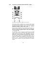
Check the jumper between “JP1” and “JP2”
(terminal designation “JUMPER”).
Only remove the cable if you want to use the UPS
in parallel operation with further PROTECT 1. units
of the same type (see also chapter 9).
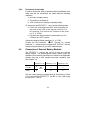
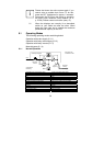
5.3.3 Preparation of the Output Cabling
Before you connect the loads to the UPS, the nominal output
listed on the nameplate must be greater than or equal to the
sum of the load power outputs.
The output of the PROTECT 1. should supply further separate
circuits in a subdistribution. Make sure that the fuse protection is
selectively designed (see also chapter 5.2.2).
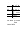
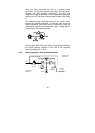
For the connection between the PROTECT 1. and the
subdistribution, cable cross-sections acc. to the table
“Connection Cross-Sections and Fuse Protection” on p. 31
must be used. In the subdistribution, note at least the following
information:
♦ Maximum permissible total load
♦ Maximum permissible load of the individual load circuits
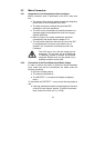
i
In the case of a common distribution cabinet
(circuits with mains as well as UPS voltage), label
each circuit with the respective supply (mains or
UPS).