


State Analysis
This chapter explains how to configure the USB
Analysis Probe to perform state analysis on the
Universal Serial Bus. The configuration software on
the flexible diskette sets up the format specification
menu of the logic analyzer for compatibility with the
USB Analysis Probe. The next chapter explains how
to configure the USB Analysis Probe to perform timing
analysis.
Installation Quick
Reference
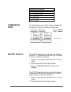
The following procedure describes the major steps
required to perform measurements with the USB
Analysis Probe module.
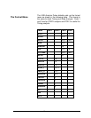
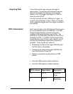
The following explains how to connect the logic
analyzer to the USB Analysis Probe for state analysis:
1. Remove the probe tip assemblies from the
logic analyzer cables.
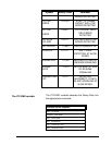
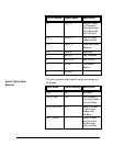
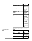
2. Plug the logic analyzer cables into the USB
Analysis Probe cable headers as shown in the
following table.
Logic Analyzer USB Analysis
Probe
Comment
Master POD 1 Header 1 State analysis
(USB_ST)
POD 2 Header 2 State analysis
(USB_ST)
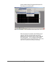
3. Plug the USB Analysis Probe IN cable to the
upstream Host or Hub. The USB Analysis
25