


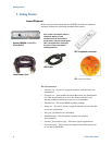
Getting Started
LED
LEDs Function
Power LED
Indicates power-on
USB Active
Indicates that the instrument is currently being
used/controlled by the user software
Signal Detect
Indicates the status of the Signal Detect line when the
inserted SFP module supports a Signal Detect Control line.
Usually this pin indicates whether the optical input power
is above or within the specified range.
Data Error
Indicates that the error detector has detected bit errors
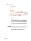
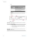
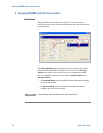
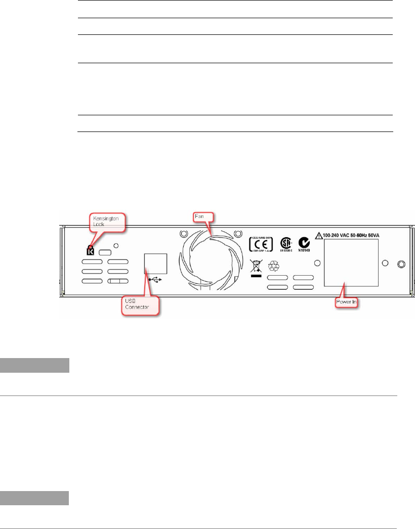
Rear Panel
The Rear Panel has the USB connector,the Power in, and the safety
symbols.
Figure 2 Rear Panel
NOTE
For proper ventilation keep the Serial BERT at a distance of 2 cm on both sides,
and 10 cm at the back.
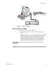
To Connect N5980A
1 Connect the N5980A power cord at the rear panel Power In.
2 Connect the instrument, via USB, to the PC on which the User
Interface will be installed.
NOTE
Some USB hubs might decrease performance. If possible, directly connect the
N5980A to your PC.
10 N5980A User Guide