


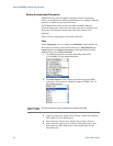
Operating N5980A with the User Interface
Setting the Instrument Parameters
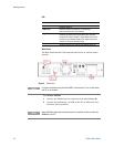
N5980A has two (SFP and SMA) integrated Pattern Generators,
which can be adjusted to different parameters, for example, different
patterns or different error insertion rates.
The N5980A Error Detector has two (SFP and SMA) different
physical input ports, while only one input port can be analyzed at a
given time. The analyzed input can be selected with the User
Software.
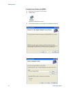
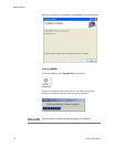
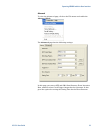
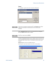
There are two setting pages, Setup and Advanced.
Setup
In the Setup page you can change, the Data Rate, which applies for
the Pattern Generator, and the Error Detector ; Data Pattern and
Logic Level for the Pattern Generator; and Data Pattern and the
analyzed Input of the Error Detector.
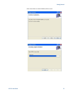
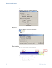
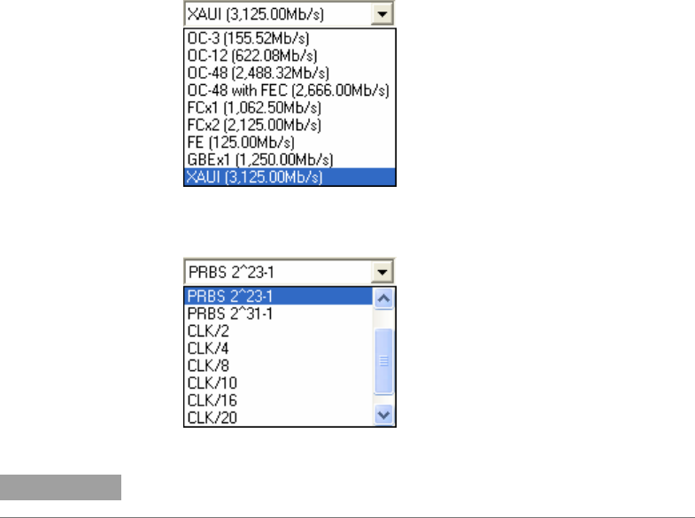
1 The following options are under Data Rate; and XAUI
[3,125.00Mb/s] is the default data rate:
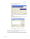
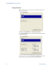
2 The Data Pattern of the Pattern Generator supports PRBS
polynoms, clock patterns, and K28.5 pattern. PRBS 2^23-1 is
the default pattern:
NOTE
Use the scroll bar to see the complete list of patterns provided.
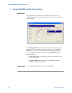
3 Logic Level has two options, ECL [850mV], and LVDS [400mV].
ECL [850mV] is the default level.
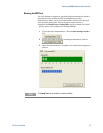
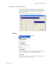
4 Error Detector Pattern. For details refer to
Error Detector.
5 Error Detector Input has two options, SMA [Electrical], and
SFP [Optical]. SMA [Electrical] is the default input for the
Error Detector.
18 N5980A User Guide