


Reference for the User Interface
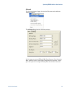
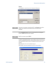
Error Detector
Data Pattern:
The Error Detector (ED) has a built in CDR for automatic clock
recovery, and phase alignment. The ED also performs automatic
polarity correction when required. Additionally it can detect the
incoming PRBS. The input for the Data Pattern has two options, SMA
[Electrical], and SFP [Optical]. SMA [Electrical] is the default input
for the Error Detector.
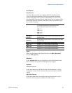
Automatic
Error Detector determines the incoming data stream
automatically. The supported data streams are:
PRBS 2^7-1
PRBS 2^15-1
PRBS 2^23-1
PRBS 2^31-1
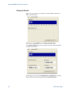
SFP (Optical
Generator)
The data pattern is taken from the current setting on the SFP
generator output.
SMA (Electrical
Generator)
The data pattern is taken from the current setting on the SMA
generator output.
PRBS 2^7-1
A PRBS 2^7-1 is used for pattern synchronization.
PRBS 2^15-1
A PRBS 2^15-1 is used for pattern synchronization.
PRBS 2^23-1
A PRBS 2^23-1 is used for pattern synchronization.
PRBS 2^31-1
A PRBS 2^31-1 is used for pattern synchronization.
Input:
There are two inputs to the Error Detector, the SMA (Electrical),
and the SFP (Optical).
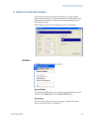
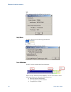
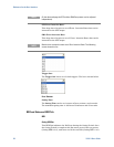
Advanced
In the Advanced tab you can separately set the Data Patterns, and
Error insertion for the SFP and SMA generator outputs.
Generator
SFP Data Pattern:
In this drop down list you have the same set of patterns, as in the
setup page, to select from. The selected pattern will affect the SFP
output.
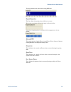
SMA Data Pattern:
In this drop down list you have the same set of patterns to select
from. The selected pattern will affect the SMA output.
N5980A User Guide 27