


Managing OmniSwitch 6600 Series Stacks Monitoring Stacks
OmniSwitch 6600 Series Hardware Users Guide April 2004 page 3-21
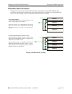
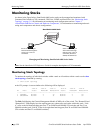
In the example on the previous page there are two switches in this stack. Switch 1, which is an OS6648,
has the primary CMM role and Switch 2, which is an OS6624, has the secondary CMM role. Switch 1’s
left-hand stacking port (Port 51) is connected to Switch 2’s left-hand stacking port (Port 27). Switch 1’s
right-hand stacking port (Port 52) is connected to Switch 2’s right-hand stacking port (Port 28). The Link
A State and Link B State fields indicate that the links between the switches are currently active and
running.
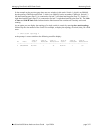
As an option you can display the topology of a single switch in a stack by entering show stack topology
followed by the slot number of the switch. For example, to display the topology of switch (slot) you would
enter
-> show stack topology 2
at the prompt. A screen similar to the following would be display:
Link A Link A Link A Link B Link B Link B
NI Role State RemoteNI RemoteLink State RemoteNI RemoteLink
---+-----------+---------+---------+-----------+---------+---------+----------
2 SECONDARY ACTIVE 1 51 ACTIVE 1 52