


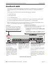
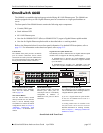
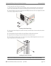
OmniSwitch 6600 Series Chassis and Hardware Components Status LEDs
OmniSwitch 6600 Series Hardware Users Guide April 2004 page 2-11
Status LEDs
LEDs provide visual status information. These “status lights” are used to indicate conditions such as
hardware and software status, primary and back up power supply status, primary and secondary status
(stacked configurations), temperature and fan errors, slot number information, link integrity, and data
flow.
Refer to the diagram below for detailed information on OmniSwitch 6600 series LED states.
Note. OmniSwitch 6600 series switches offer the same LED status indicators. For information on uplink
module LEDs, refer to page 2-25. For information on stacking module LEDs, refer to page 2-28.
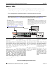
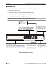
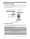
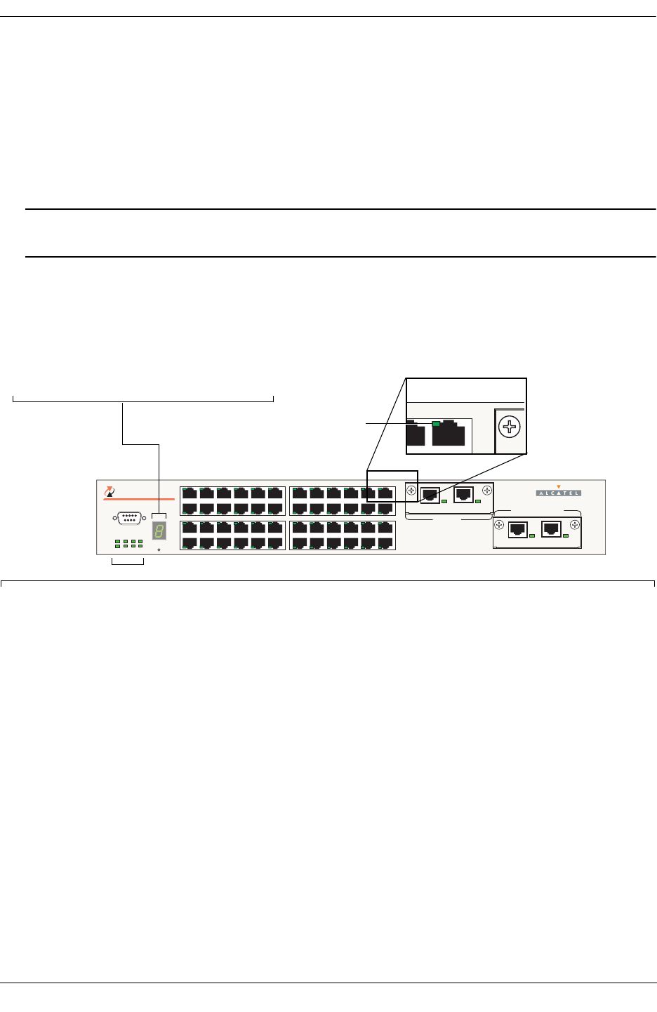
Front Panel LED Descriptions (OS6648 Shown)
CONSOLE
3
4
5
6
7
8
9
10
11
12
13
14
15
16
17
18
19
20
21
22
23
24
1
2
EXPANSION/STACKING
EXPANSION
49 50 51 52
TM
OmniSwitch 6648
OK1
OK2
PS1
PS2
PRI
SEC
TEMP
FAN
27
28
29
30
31
32
33
34
35
36
37
38
39
40
41
42
43
44
45
46
47
48
25
26
LINK/ACT
LINK/ACT
LINK/ACT
LINK/ACT
SEL
4
547
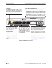
Temperature Management
LEDs
TEMP. Displays solid green
when the switch is operating
within the allowed temperature
range; displays solid amber if a
temperature error occurs (i.e.,
the switch is operating outside
the temperature range).
FAN. Displays solid green
when all fans in the fan tray
are running at normal speed.
Displays solid amber if a fan
error occurs (i.e., one or more
fans are not running at normal
speed).
Hardware and Software
Status LEDs
OK1. Hardware Status. Dis-
plays solid green when pow-
ered on and the switch has
passed hardware diagnostic
tests. Displays solid amber
when powered on and the
switch has failed hardware
diagnostic tests.
OK2. Software Status. Blinks
green when the switch’s sys-
tem management software is
operational. Displays solid
amber when a system soft-
ware failure occurs. Blinks
amber when the software is in
a transitional state (e.g., when
software is being downloaded
to the switch).
Power Supply LEDs
PS1. Displays solid green
when the primary (i.e., factory-
installed) power supply status
is OK and the power supply is
operating normally. Displays
solid amber in the unlikely
event of a power supply fail-
ure.
PS2. Displays solid green
when the optional redundant
power supply status is OK and
the power supply is operating
normally. Displays solid amber
if no redundant power supply
is installed or in the unlikely
event of a redundant power
supply failure.
Slot Indicator LED
The slot indicator LED is manually configurable
and displays the switch’s current slot number in a
stacked configuration (i.e., 1 – 8). For detailed
information on manually setting the switch’s slot
number, refer to Chapter 3, “Managing
OmniSwitch 6600 Series Stacks.”
Ethernet Port LEDs
Each Ethernet port has a built-in corresponding LED. This
LED indicates the link and activity status for each Ethernet
port. The LED displays green when a valid Ethernet cable
connection exists. Flashes green as data is transmitted or
received on the port.
LED Location
Stack LEDs
PRI. Displays solid green
when if the switch is either a
stand-alone switch or the pri-
mary switch in a stack; other-
wise, if the switch status is
secondary or idle, this LED is
off.
SEC. Displays solid green if
the switch is the secondary
switch in a stack; otherwise,
this LED is off.