


Managing OmniSwitch 6600 Series Stacks Setting Up a Stacked Configuration
OmniSwitch 6600 Series Hardware Users Guide April 2004 page 3-13
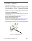
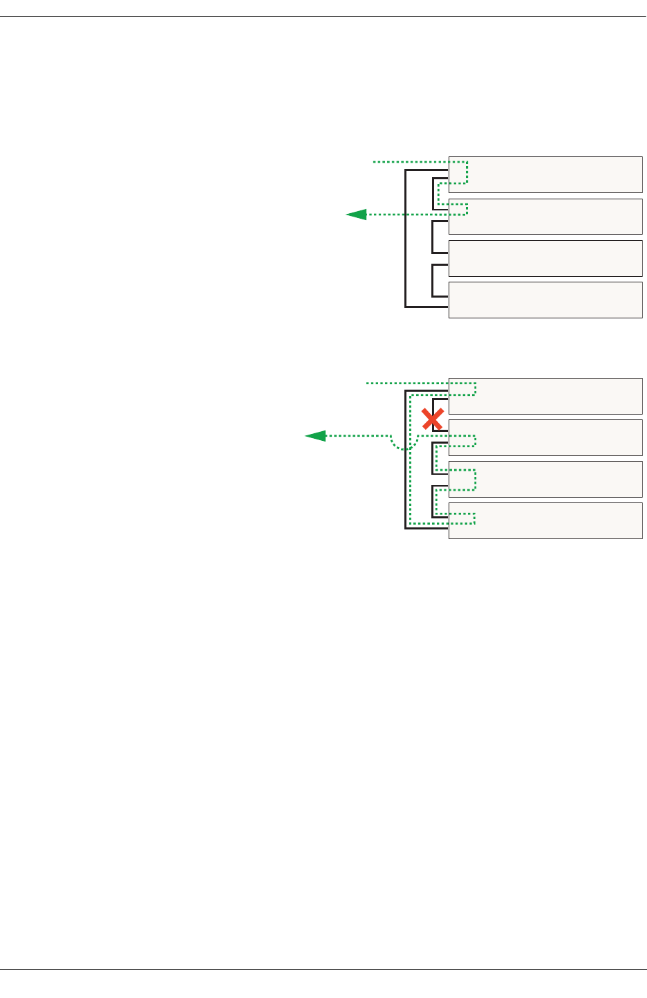
Redundant Stack Connection
The figure below shows how the redundant connection (provided by the OS66STK-CBL1M cable)
between the top and bottom switches in the stack ensures that data will continue to flow throughout the
stack, even in the unlikely event of a connection failure between two switches.
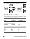
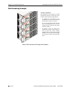
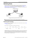
Stacking Cable Redundancy Example
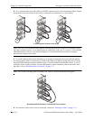
Switch 1
Switch 2
Switch 3
Switch 4
No Connection Failure
In this example, there is a VLAN with an ingress port on
switch 1 and an egress port on switch 2.
Data enters switch 1 via a 10/100 Ethernet port, then is
passed to switch 2 over the OS66STK-CBL30 stacking
cable connection, then exits switch 2 via a 10/100 Ether-
net port.
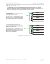
Connection Failure Between Switches 1 and 2
Here, the stacking connection between switches 1 and 2
has gone down unexpectedly. Data can no longer travel
directly between switches 1 and 2.
However, because there is a redundant connection (the
OS66STK-CBL1M cable between switches 1 and 4),
data is passed to switch 4, then quickly traverses switch 3
and exits switch 2 to its destination.
Switch 1
Switch 2
Switch 3
Switch 4