


Chapter 2: Installation
28
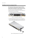
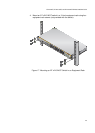
Installing the Switch in an Equipment Rack
Note: These instructions show you how to install an AT-x210-9GT,
AT-x210-16GT or AT-x210-24GT switch in an equipment rack. Rack
mount kit brackets are included with AT-x210-16GT and AT-x210-24GT
switches. The AT-x210-9GT switch is installed in a rack with the optional
AT-x210-9GT rack mount kit (Part Number 990-003904-00).
To install AT-x210-9GT, AT-x210-16GT or AT-x210-24GT switches in a
19-inch equipment rack, follow these steps:
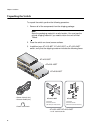
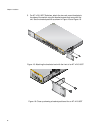
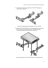
1. Place the unit upside down on a level, secure surface.
Figure 15. Turning the Switch Upside Down
2. Unscrew the rubber feet from the bottom and turn the switch over.
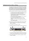
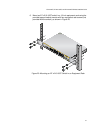
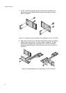
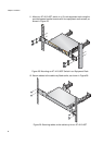
3. For AT-x210-24GT Switches, attach two rack mount brackets to the
sides of the switch using the bracket screws that come with the unit.
Figure 16. Attaching brackets to an AT-x210-24GT
1971
5
7
6
8
91113
15R
10
12
14
16R
17
19 21
23R
18
20 22
24R
15 16
23
24
24
6
8
RS-232
FAULT
STANDBY
SELECT
13
57
9
11 15R
17
15
16
23
24
SPEED
MODE
MODE
L/A
LINK /
ACT
L/A
LINK /
ACT
SFP
1
3
5
7
2
46
8
9
11
13
15R
10
12 14
16R
17
19
21
23R
18
20
22
24R
AT-x210-24GT
Gigabit Ether
net Switch
15
16
23
24
L/A
24
6
8
10
12 14
16R
18
20
22
24R
MODE
L/A
MODE
CONSOLE
RS-232
FAULT
STANDBY
RESET
POWER
SELECT
1
3
57
911
13
15R
17
19
2123R
15
16
23
24
SPEED
DUPLEX
MODE
MODE
SPEED / DUPLEX
L/A
LINK /
ACT
L/A
LINK /
ACT
SFP
CLASS 1
LASER PRODUCT