


Chapter 2: Installation
30
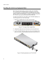
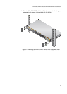
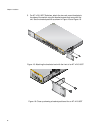
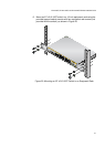
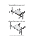
5. For AT-x210-16GT Switches, attach the two rack mount brackets to
the sides of the switch using the bracket screws that come with the
unit. See the bracket position as shown in Figure 18 and Figure 19.
Figure 18. Attaching the brackets level with the front of an AT-x210-16GT
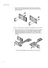
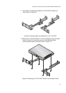
Figure 19. Close up showing a bracket positioned for an AT-x210-9GT
1
3
5
7
2
4
6
8
911
13
15R
10
12 14 16R
FAULT
STANDBY
RESET
POWER
CONSOLE
RS-232
SELECT
SPEED
DUPLEX
2
4
6
8
10
12
14
16R
1
3
5
7
9
11
13
15R
L/A
MODE
L/A
MODE
15
16
15
16
AT-x210-16GT
Gigabit Ether
net Switch
MODE
SPEED / DUPLEX
L/A
LINK /
ACT
MODE
L/A
LINK /
ACT
SFP
CLASS
1
LASER PRODUCT
15
16
15
16
AT-x210-16GT
Gigabit Ether
net Switch
L/A
LINK /
ACT
SFP
CLASS 1
LASER PRODUCT