


Chapter 2: Installation
32
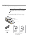
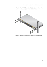
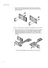
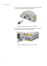
7. For AT-x210-9GT switches, first fit the rack mount handles to the
brackets using the supplied M3x6mm pan head screws, as shown
below in Figure 21.
Figure 21. Fitting rack mount handles to the brackets for an AT-x210-9GT
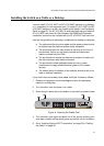
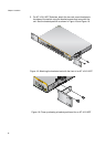
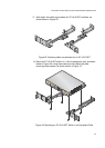
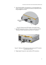
8. After fitting the rack mount handles to the brackets using the supplied
M3x6mm pan head screws , as shown about in Figure 21, fit these
brackets with handles to the mounting for AT-x210-9GT switches
using the supplied M4x6mm countersunk screws, as shown below in
Figure 22.
Figure 22. Fitting brackets to the mounting for an AT-x210-9GT