


AT-x210-9GT, AT-x210-16GT, and AT-x210-24GT Switches Installation Guide
iii
Contents
Preface............................................................................................................................................................... 1
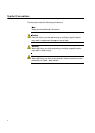
Symbol Conventions .................................................................................................................................... 2
Contacting Allied Telesis.............................................................................................................................. 3
Chapter 1: Overview
Features ............................................................................................................................................................. 6
Twisted Pair Ports ................................................................................................................................. 6
SFP Slots............................................................................................................................................... 6
LEDs...................................................................................................................................................... 7
Installation Options ................................................................................................................................ 7
Power Conservation .............................................................................................................................. 7
MAC Address Table .............................................................................................................................. 7
Package Contents........................................................................................................................................ 8
Front and Back Panels................................................................................................................................. 9
Management Software............................................................................................................................... 11
Twisted Pair Ports...................................................................................................................................... 12
LEDs .......................................................................................................................................................... 13
POWER/FAULT/STANDBY LEDs....................................................................................................... 13
10Base-T/100Base-TX/1000 Base-T Link Activity LEDs..................................................................... 15
SFP LEDs............................................................................................................................................ 17
Power Supply............................................................................................................................................. 19
Chapter 2: Installation
Reviewing Safety Precautions.......................................................................................................................... 22
Selecting a Site for the Switch ................................................................................................................... 24
Cable Specifications................................................................................................................................... 25
Unpacking the Switch................................................................................................................................. 26
Installing the Switch on a Table or a Desktop............................................................................................ 27
Installing the Switch in an Equipment Rack ............................................................................................... 28
Installing Optional SFP Transceivers......................................................................................................... 35
Cabling the Switch ..................................................................................................................................... 39
Powering On the Switch............................................................................................................................. 41
Monitoring the Initialization Processes....................................................................................................... 43
Chapter 3: Troubleshooting
Appendix A:
Physical Specifications..................................................................................................................................... 52
Dimensions.......................................................................................................................................... 52
Weight ................................................................................................................................................. 52
Environmental Specifications..................................................................................................................... 52
Power Specifications.................................................................................................................................. 53
Electrical Safety and Electromagnetic Emissions Certifications ................................................................ 53
Connectors and Port Pinouts ..................................................................................................................... 54