


Layer 2 Switching 33
Rapier Switch Software Release 2.2.1
C613-02013-00 Rev A
If the value NONE or 0 is specified, then packet rate limiting for multicast
packets is turned off. If any other value is specified, the reception of multicast
packets will be limited to that number of packets per second. See the note after
the BCLIMIT parameter description for important information about packet
rate limiting. The default value for this parameter is NONE. If packet storm
protection limits are set on the switch, the PORT parameter must specify
complete processing blocks.
The ability of the switch to limit packet reception rates for different classes of packets is
dependent on the particular switch hardware. In particular, groups of ports may have to
have the same limits set, and the same limit may be set for the different types of packets,
depending on the hardware. Whenever packet rate limits are set on switches which have
this type of constraint, the latest parameter values entered will supersede earlier values.
When a command entered for specified ports changes the parameters for other ports, a
message will indicate these changes.
For the Rapier 16 and 24-port switches, packet storm protection limits cannot be set for
each individual port on the switch, but can be set for each processing block of ports. The
processing blocks are sets of 8 ports (e.g. as many as are applicable of ports 1-8, 9-16 and
17-24) and each uplink port is a further processing block. Therefore, a 16-port switch has
four processing blocks and a 24-port switch has five. The two uplink ports are numbered
sequentially after the last port, and therefore are 17 and 18 for a 16-port and 25 and 26
for a 24-port switch. Only one limit can be set per processing block, and then applies to
all three packet types. Thus each of the packet types are either limited to this value, or
unlimited (NONE).
For the Rapier G6 series switches, each port is a processing block, and therefore packet
storm protection limits can be set for each port individually.
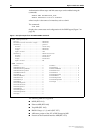
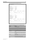
The SHOW SWITCH PORT command displays the packet storm protection
settings (Figure 8 on page 28).
SHOW SWITCH PORT=port-list
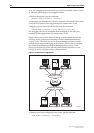
Port Mirroring
Port mirroring allows traffic being received and transmitted on a switch port to
be sent to another switch port, the mirror port, usually for the purposes of
capturing the data with a protocol analyser. This mirror port is the only switch
port which belongs to no VLANs, and therefore does not participate in any
other switching. Before the mirror port can be set, it must be removed from all
VLANs except the default VLAN. The port cannot be part of a trunk group.
To set the mirror port (and remove it from the default VLAN) use the
command:
SET SWITCH MIRROR={NONE|port}
If another port was previously set as the mirror port, this command returns the previous
mirror port to the default VLAN as an untagged port. Return this port to any VLANs
to which it should belong, using the ADD VLAN PORT command, or set it as a tagged
port using the SET VLAN PORT command if required.
Either traffic received on a port or traffic transmitted by the port, or both, can
be mirrored. This setting and the source port(s) from which traffic is sent to the
mirror port are specified using the command:
SET SWITCH PORT={port-list|ALL} MIRROR={NONE|RX|TX|BOTH}