


48 Rapier Switch User Guide
Rapier Switch Software Release 2.2.1
C613-02013-00 Rev A
Quality of Service
The switch hardware has a number of Quality of Service (QOS) egress queues
that can be used to give priority to the transmission of some frames over other
frames on the basis of their user priority tagging. The user priority field in an
incoming frame (with value 0 to 7) determines which of the eight priority levels
the frame is allocated. When a frame is forwarded, it is sent to a QOS egress
queue on the port determined by the mapping of priority levels to QOS egress
queues. All frames in the first QOS queue are sent before any frames in the
second QOS egress queue, and so on, until frames in the last QOS egress queue,
which are only sent when there are no frames waiting to be sent in any of the
higher QOS egress queues.
The mapping between user priority and a QOS egress queue can be configured
using the command:
SET SWITCH QOS=P1,P2,P3,P4,P5,P6,P7,P8
The switch has four QOS egress queues. It has a default mapping of priority
levels to QOS egress queues as defined in IEEE Standard 802.1Q (Table 7).
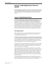
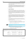
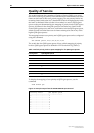
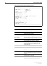
To display the mapping of user priority to QOS egress queues, use the
command:
SHOW SWITCH QOS
Figure 13: Example output from the SHOW SWITCH QOS command
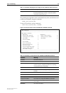
Table 7: Default priority level to queue mapping for four QOS egress queues
Priority level QOS Egress Queue
01
10
20
31
42
52
63
73
Priority Level QOS egress queue
-------------------------------------
0 ................... 1
1 ................... 0
2 ................... 0
3 ................... 1
4 ................... 2
5 ................... 2
6 ................... 3
7 ................... 3