


MATRIX SWITCHERS
9
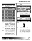
PRESS FUNCTION
F1
Selects input
(confirmed by “ON” LED)
F2
Selects output
(confirmed by “ON” LED)
F1+HOLD
Connects selected input
to selected output
F2+HOLD
Connects selected input
to selected output
F1+F2 together
(Press & Release)
Resets selected input
and output channels
F1+F2+HOLD
(Press & Hold)
Resets switcher and
loads memory #1 setting
after a series of beeps
F1 or F2 + HOLD
(All input LED’s OFF)
Disconnect selected
output
F1+HOLD+Power ON
Initializes baud rate,
input-output connections
and clears memory after
a series of beeps
F2+HOLD+Power ON
Initializes matrix size to
16x16 and offset to 00
for input and output
Table 2. Summary of F1 and F2 functions
7.2 RS-232 CONTROL OF THE SWITCHER
The HOMERUN Matrix Switcher has many
advanced remote control capabilities which are
accessible through a standard RS-232 port
through terminal block connectors provided on
the back of the module. The actual controlling
can be accomplished through a computer,
control system or any other device capable of
sending RS-232 commands.
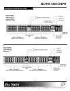
The function of each pin is described on the back
panel next to the connector. Each module has its
own RS-232 port. However, only one port should
be used to control all units, if they are attached
through loop cables.
Test each module outside of the rack prior to
installation to insure that you have established
communication.
7.2.1 RS-232 PROTOCOL:
The RS-232 protocol for the HOMERUN Matrix
Switcher uses a simple ASCII character format.
1. Square brackets “[“ & “]” are part of the
command, unless they are changed
through the [CODEn] command.
2. Use uppercase letters for all commands.
3. Make sure that the transmit pin of the
control system is connected to the
receive pin of the switcher and
connection done as per Table 1.
4. Make sure that there is a delay of 50 ms
between two consecutive commands.
The factory default settings are 2400 baud, 8
bits, 1 stop, and no parity. There is no software
or hardware flow control implemented.
The HOMERUN Matrix Switcher requires 50ms
of processing time after each command is
sent. So please keep a 50ms delay between
two consecutive commands except the [RSET]
command, which requires 1 second of
processing time.
Example: [RSET]*, wait 1 second, * [I01O02]*
wait 50ms, *[I12O09]*
The RS-232 input has a 16-character buffer
and will not execute any command longer than
16-characters. Any additional commands are
ignored until the previous command is fully
processed. After processing a valid command
an [OK] string will be returned, if requested by
the feedback command. If an invalid command
is entered the [ERR] string will be returned if
requested by the feedback command.
7.2.2 PROGRAMMING COMMANDS
NOTE:
These programming commands are used for
programming the switcher; they should not be
used as part of a program to operate the
switcher. The programming setting changes
done through these commands are stored in a
non-volatile memory. Typically these
commands can be issued 10,000 times before
the memory needs to be replaced.
[SETIDn]
n = level/module ID number; 0 to 9