


MATRIX SWITCHERS
22
at the same
time, can this
be done with
this product?
a challenge to connect.
8
Can I use
contact closure
to control the
switcher?
No. The unit should be
controlled using RS-232
commands or through the
optional
CP-01/CP-02/CP-03
9
Is the
HOMERUN
Switcher
capable of
controlling
various
projectors?
It is not recommended in
large size systems to
control a projector through
the switcher. It is expected
that a control system is
available to control both
switcher and projector or
projectors independently. If
a control system is not
being used, the switcher
can be connected to the
projector and control
commands can be passed
through the switcher to the
projector. Call Altinex for
programming information.
TROUBLESHOOTING GUIDE 10
• First, make sure, that power is connected into
the power input connector and input power is
within the range of 90-260 VAC.
• Make sure that cables are connected properly
and snugly. Please immediately replace any
defective or damaged cables.
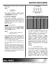
• If an RS-232 connection is used to control the
HOMERUN Switcher, then please make sure
that the connection to each pin of the RS-232
port located on the back of the unit is described
in Table 1.
• In the Video module please make sure that the
Input level of the Video signal RGB is 1.2 V p-p.
In the Audio module the Input level of the Audio
signal is 5 V p-p.
• If the RS-232 control, or Front Panel CP-01, or
Touch LCD CP-03 control is not working or
responding, please verify that the unit works
through Back Panel switches F1 and F2. If the
HOMERUN Switcher is working properly
through the Back panel, please verify that
control cable connections are connected to the
control system, and sources and displays are
properly connected.
• If a control system is used to control the
switcher through an RS-232 port, make sure
that, there is at least a 50 ms delay between two
adjacent commands being sent. Also make sure
that all commands have a Square bracket ‘[‘
before and “]” after each command.
• Please verify that the correct ID number is
assigned to each unit. If a particular group of
modules needs to be controlled then the unit ID
number must be same for all the modules in
that group. Unit ID number 0 will have the
HOMERUN Switcher unit not respond to any
command, while unit ID number 1 in the
command will have all units follow the
command.
• If you are using RS-232 control for this unit,
please follow connection instructions as
described in the manual and verify operation
with the downloaded software for PC’s from the