


MATRIX SWITCHERS
17
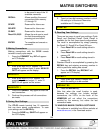
Press the RECALL button and hold for 2
seconds. The unit will beep and switch into the
recall mode. This mode is indicated by the
RECALL LED flashing slowly. Press INPUT 1
through INPUT 16 to recall the desired memory
location. Output buttons do not work anymore in
this operation.
Press and hold the RECALL button for 2 sec.
again to disable the recall function.
Disable/Enable Front Panel:
Press the OUT SEL button and hold it for 2
seconds. The front panel will be disabled. Press
and hold it again to enable the front panel.
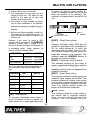
Preview of Connection
When any output is selected through the Front
Panel CP-01 buttons, the input/inputs that are
connected to that particular output will show its
LED ON. Similarly if any input is selected on the
Front Panel CP-01, then the output to outputs
connected to this input will show a flashing LED.
PROGRAMMING OPERATION
This programming operation is only performed
for changing module settings and should not be
part of a general control operation. All the
HOMERUN modules that are connected through
a loop cable to the HOMERUN Switcher module
with a CP-01 Front Panel will be reprogrammed.
Enable Vertical interval switching:
This function operates only if the VIS function is
installed. Press the SETUP button. The SETUP
LED will start to flash. Press OUT 7 to enable the
VIS function. The VIS function operates only with
NTSC or PAL type video signals. Input #1 is the
reference input for the purposes of VIS
switching. If Input #1 is not present the
HOMERUN will switch without VIS even though
VIS is enabled.
Disable vertical interval switching:
This function operates only if the VIS function is
installed. Press the SETUP button. The SETUP
LED will start to flash. Press OUT 8 to disable
the VIS function.
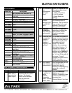
Set Unit ID numbers
This function is used to control individual levels
of the HOMERUN Matrix Switcher, such as
switching video and audio separately. If the
HOMERUN Switcher is set to unit ID 1 then the
switcher will respond to all commands through
the RS-232 port regardless of the UID command.
The factory default is unit ID =1.
To set the unit ID number, press the SETUP
button. The SETUP LED will start to flash. Press
the OUT1 through OUT6 buttons to select the
proper unit ID number. The switcher will reset
after this operation.
This command will set unit ID numbers on the
master unit and also on all units attached to the
master unit.
Therefore only the units that need to have
changes in unit ID number should be attached to
the master unit during the set-up phase through
the loop cable.
Suggested Unit ID assignment if individual
control is required:
Unit ID 2 Red, Green and Blue channels (All
three channels should have the
same Unit ID number)
Unit ID 3 Horizontal, Vertical or Composite
sync channels (All sync channels
should have the same Unit ID
number)
Unit ID 4 Composite video signal channel
Unit ID 5 S-Video type video signal channels
(Both Luma and Chroma should
have the same Unit ID numbers)
Unit ID 6 Left and right audio channels should
have the same Unit ID numbers.
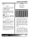
SETUP +OUT 1 UNIT ID #1
SETUP +OUT 2 UNIT ID #2
SETUP +OUT 3 UNIT ID #3
SETUP +OUT 4 UNIT ID #4
SETUP +OUT 5 UNIT ID #5
SETUP +OUT 6 UNIT ID #6