


MATRIX SWITCHERS
8
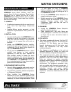
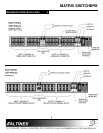
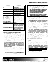
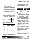
Figure 2: HOMERUN Video Module
OPERATION 7
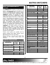
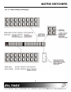
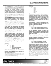
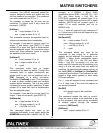
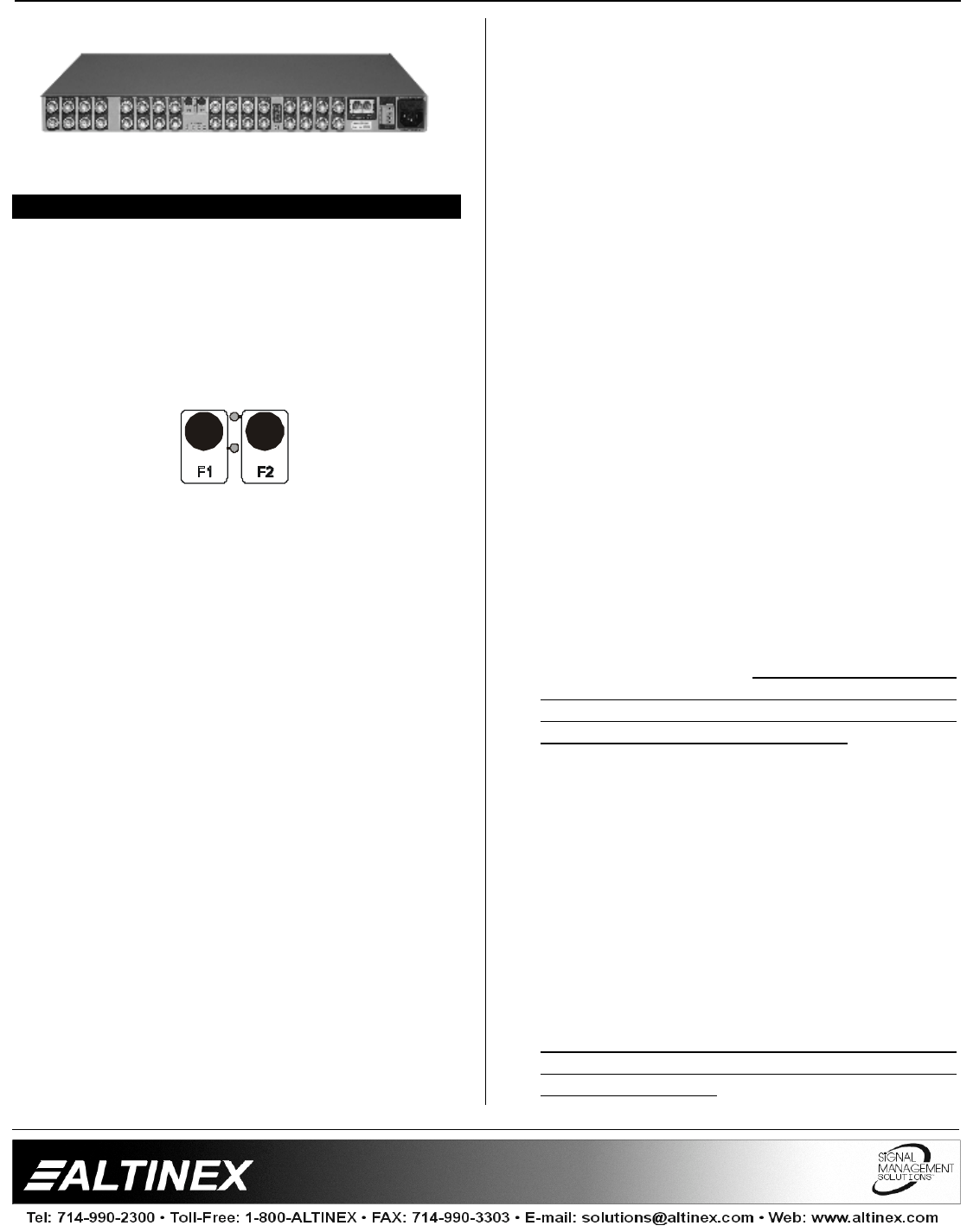
7.1 BACK PANEL MANUAL CONTROL
Two switches (F1 and F2) are provided in the
center of the back panel as shown below. During
installation or troubleshooting these switches
provide a simple manner of controlling the
module from the back of the rack.
Figure 3: Back Panel control switches
SELECT INPUT: With the F1 switch, the desired
input is selected by pressing the switch until the
LED of the selected input is lit. As F1 is
repeatedly pressed, the switcher scrolls through
each of the inputs and the corresponding LED is
lit.
SELECT OUTPUT: With the F2 switch, the
desired output is selected by pressing the switch
until the LED of the selected output is lit. As F2 is
repeatedly pressed, the switcher scrolls through
each of the outputs and the corresponding LED
is lit.
CONNECT INPUT to OUTPUT: To connect the
selected input to the selected output, simply hold
either F1 or F2 for 2 seconds until you hear a
beeping sound. This operation can be repeated,
as many times as needed, until all desired inputs
are connected to all desired outputs.
DISABLE SELECTED OUTPUT: Press F1 until
all input LED's are OFF. This occurs when the
input positioned between input 16 and input 1 is
selected. Select the output that you want to
disable and hold F1 or F2 for approximately 2
seconds until you hear a beeping sound and
release the button. This will disable the selected
output.
RESET SELECTED CHANNELS: Press the F1
& F2 switches simultaneously and release them
quickly to reset the connection of the selected
input & output.
RESET TO DEFAULT: To reset the unit to its
default status (power-on stage) press and hold
the F1 & F2 switches simultaneously for
approximately three seconds until you hear a
beeping sound. This will disconnect all current
inputs and outputs and load settings stored in
memory location #1. If memory location #1 is
empty it loads the condition where there is no
input is connected to any output.
INITIALIZE MATRIX SIZE AND OFFSET TO
FACTORY DEFAULT: To initialize the matrix
size and offset of the switcher to the factory
default, a POWER ON function must be used
through switch F2. First turn OFF the unit. Then
while pressing down the F2 switch, turn the
power ON for the unit. Wait until several beeps
are heard and then release the F2 switch. This
step will initialize the matrix size to 16x16 and the
offset for both input & output to 0.
This step will not clear the memory or disconnect
the inputs and outputs. This procedure is used
for resetting the switcher to factory matrix and
offset default condition and should not be part of
the program to operate the switcher.
INITIALIZE MEMORY & BAUD RATE TO
FACTORY DEFAULT: To initialize the
connection memory and communication baud
rate, a POWER ON function must be used
through switch F1. To initialize the unit without
changing the size and offset; first turn the unit
OFF. Then while holding down the F1 switch,
turn the unit back ON. Wait until several beeps
are heard before releasing the F1 switch. This
step will disconnect all inputs from outputs, clear
all memories and set the baud rate to 2400 for
RS-232 communication.
This procedure is used to initialize the switcher
and should not be part of the normal program to
operate the switcher.