


MULTI-TASKER™
400-0131-004
16
16
23. [TEST]
This command performs a test on the internal
memory. Upon completion, the system will
display the results. If there are no problems, the
system will display the following:
MEMORY IS GOOD
Otherwise, failures will be indicated.
Command Format: [TESTCnUi]
Cn = Card ID (n = slot # from 1 to max slots)
Ui = Unit ID (i = # from 0 to 9)
Example:
There is an MT105-100/101 in slot 10. In order
to test the internal memory, send the command
[TESTC10].
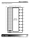
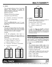
24. [MATmXy]
This matrix command allows the matrix switcher
to be setup for different matrix sizes. The tables
below show how the inputs and outputs will be
configured when the matrix is changed.
Example:
In the 8x4 configuration, when Input 1 is
connected to Output 8, the entire channel, 1a
and 1b, will be switched to outputs 8a and 8b
respectively.
Command Format: [MATmXyCnUi]
m = number of inputs (m = 16, 8 or 4)
y = number of outputs (y = 8, 4 or 2)
Cn = Card ID (n = slot # from 1 to max slots)
Ui = Unit ID (i = # from 0 to 9)
16 X 8 8 X 4
IN OUT IN OUT
O9 O1 O1 O5a O1a O1a
O10 O2 O2 O5b O1b O1b
O11 O3 O3 O6a O2a O2a
O12 O4 O4 O6b O2b O2b
O13 O5 O5 O7a O3a O3a
O14 O6 O6 O7b O3b O3b
O15 O7 O7 O8a O4a O4a
O16 O8 O8 O8b O4b O4b
4 X 2
IN OUT
O3a O1a O1a
O3b O1b O1b
O3c O1c O1c
O3d O1d O1d
O4a O2a O2a
O4b O2b O2b
O4c O2c O2c
O4d O2d O2d
25. [HELP]
This command displays information available for
the Multi-Tasker interface commands.
Command Format: [HELPCnUi]
Cn = Card ID (n = # from 1 to max slots)
Ui = Unit ID (i = # from 0 to 9)
Example:
In order to display the RS-232 commands
available for the MT105-100/101 card in slot 4,
send the command [HELPC4]. The commands
along with a brief description will be displayed in
the terminal window.
GROUP COMMANDS
The next few commands are group commands.
The use of groups allows several boards, with the
same functions, to be controlled simultaneously
with a single command. These commands apply to
all cards, not only the MT105-100/101.
26. [WR]
This command groups multiple cards in the
enclosure allowing all the group members to be
controlled simultaneously with the same
command. Each Multi-Tasker™ unit may define
a maximum of eight groups.
In Multi-Tasker™ systems with audio and video
cards, boards are typically grouped as follows:
Group 1 = Video Cards
Group 2 = Audio Cards
Group 3 = Video and Audio Cards