


MULTI-TASKER™
400-0131-004
8
8
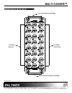
INSTALLING YOUR MT105-100/101 6
Step 1. Turn off power to the Multi-Tasker™
enclosure.
Step 2. Slide the MT105-100/101 into an available
slot in the Multi-Tasker™ enclosure in
order to connect to the bus. Make sure
that the MT105-100/101 card fits into
place. Secure the card to the
Multi-Tasker™ by tightening the retainer
screws located on the top and bottom of
the MT105-100/101 card.
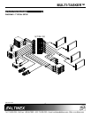
Step 3. Turn on power to the Multi-Tasker™
enclosure.
Step 4. Connect a coaxial cable from the video
source to the input connector of the
MT105-100/101. Connect the output
connectors of the MT105-100/101 to the
display devices through a coaxial cable.
Step 5. Starting from the left, identify the slot
number where the MT105-100/101 card is
plugged into the Enclosure and note that
it is for RS-232 control.
OPERATION 7
7.1 RS-232 CONTROL
The MT105-100/101 has many advanced remote
control capabilities, which are accessible through
standard RS-232 communication. Actual control
may be accomplished through a computer control
system or any other device capable of sending
RS-232 commands.
7.1.1 RS-232 INTERFACE
The RS-232 commands, for the MT105-100/101
are in a simple ASCII character format.
1. Square brackets “[ ]” are part of the
command.
2. Use uppercase letters for all commands.
The cards in a Multi-Tasker™ system are
capable of performing various functions, as well
as providing feedback to the user or control
system. Commands instruct a card to perform
specific actions or request information about the
status of the card. Some commands do both at
the same time.
A command that instructs the card to simply
perform an action will generate feedback of “[ ]”.
The open and close brackets indicate the card
received a valid command. If the command
requested information from the card, the
feedback generated by the card is the
acknowledgement of having received a valid
command. Invalid commands generate
feedback of “[ERR001]”.
After processing a command, an “OK” or
[ERR001] will be returned as feedback if “F” is
included at the end of a command string.
Commands ending in “S” will be saved into
memory. Commands not ending in “S” will still
be executed but will not be restored when the
system is reset or powered off then on.
7.2 DESCRIPTION OF COMMANDS
Each command consists of three parts:
Function, Card ID, and Unit ID.
[ Function , Card ID , Unit ID ]
Example: [VERC3U2]
VER = Function
C3 = Card ID or Group ID
U2 = Unit ID
For Function, see a detailed explanation under
each command description.
The Card ID is a unique identifier. It is equal to
the enclosure slot number, or it may be an
assigned value. As the slot number, the value
can range from 1 to 4 up to 1 to 20 depending
on the enclosure. If the value is assigned, the ID
may be a maximum of 99.
Card ID 0 (C0) is used for the controller and
cannot be reassigned.