BreezeNET DS.11 Series User Manual
C-4
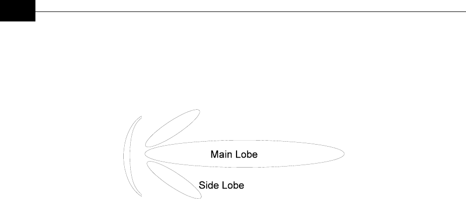
Directional Antenna
Radiates and receives most of the signal power in one direction. The following
diagram shows the radiation pattern of a directional antenna with its side lobes in
polar form:
Figure C-5: Radiation Pattern of Directional Antenna
Antenna Beamwidth
The directiveness of a directional antenna. Defined as the angle between two half-
power (-3 dB) points on either side of the main lobe of radiation.
System Characteristics
Receiver Sensitivity
The minimum RF signal power level required at the input of a receiver for certain
performance (e.g. BER).
EIRP (Effective Isotropic Radiated Power)
The antenna transmitted power. Equal to the transmitted output power minus
cable loss plus the transmitting antenna gain.
P
out
- Output power transmitted in dBm
Ct - Transmitter cable attenuation in dB
Gt - Transmitting antenna gain in dBi
Gr - Receiving antenna gain in dBi
Pl - Path loss in dB
Cr - Receiver cable attenuation in dB
Si - Received power level at receiver input in dBm
Ps - Receiver sensitivity in dBm
Si = P
out
- Ct + Gt - Pl + Gr - Cr
EIRP = P
out
- Ct + Gt


