


American DJ® - www.americandj.com - Accu Roller 250™ Instruction Manual Page 31 American DJ® - www.americandj.com - Accu Roller 250™ Instruction Manual Page 32
Operating Modes: The Accu Roller 250™ can operate in three
different modes. This next section will detail the differences in
the operating modes.
• Stand alone mode -
The unit will react to sound, chasing through the built-in programs.
• Master/Slave mode -
You can daisy chain up to 16 units together to
get a synchronized
light show without the need of an external controller. The units will
react to sound chasing through the several built-in programs.
• DMX control mode -
This function will allow you to control
each individual fixtures traits
with a standard DMX
-512 controller such as the Elation® Show
Designer.
™
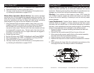
Universal DMX Control: This function allows you to use a uni-
versal DMX-512 controller such as the Elation
® DMX Operator™
or Elation
® Show Designer™ to control head movement, the color
wheel, gobo wheel, and the shutter (strobe). A DMX controller allows
you to create unique programs tailored to your individual needs.
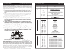
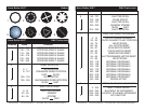
1. The Accu Roller 250™ uses eight DMX channels. See pages 36-
38 for detailed description of the DMX traits.
2. To control your fixture in DMX mode, follow the set-up procedures
on pages 12-14 as well as the set-up specifications that are
included with your DMX controller.
3. Use the controller’s faders to control the various DMX fixture traits.
4. This will allow you to create your own programs.
5. Follow the instruction on page 17 to set the DMX address.
6. For longer cable runs (more than a 100 feet) use a terminator on
the last fixture.
7. For help operating in DMX mode consult the manual included
with your DMX controller.
Stand-Alone Operation (Sound Active): This mode allows a
single unit or several units linked together, to run to the beat of the
music.
1. Access the main menu.
2. Tap the UP button until
“AUDI” is displayed, and Press ENTER.
Accu Roller 250™ Operation Accu Roller 250™ Editing Program
Editing procedure 2: Using an external controller.
1. Access the main menu.
2. Tap the UP button until “EDIT” is displayed. Press ENTER.
3. The display will show “SC01”, this stands for the scene
number to be edited. For example: If “SC01” is displayed, you
will be editing scene 1.
4. Change the scene number by pressing the UP button.
5. Press ENTER, the display will show “C-01”, the “1” stands for
the channel number 1.
6. Press the UP button until “CEDT” is displayed, press ENTER.
7. The display will show “OFF”, press the UP button so that “ON”
is displayed, press ENTER.
8. The display shows “SC02”. You have successfully down-
loaded the first scene.
9. Adjust the Step-time. needed by pressing the UP button.
10. Call up the second scene in your controller now.
11. Repeat steps 3-6 until all desired scenes are downloaded.
12. Press MODE/ESC to exit. The number of steps can be
defined under “Step” and the scenes can be called up under
“Run”.