


American DJ® - www.americandj.com - Accu Roller 250™ Instruction Manual Page 11 American DJ® - www.americandj.com - Accu Roller 250™ Instruction Manual Page 12
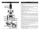
Accu Roller 250™ Controls and Functions
10. Lamp Assembly and Access Plate - This plate accesses the lamp
socket assembly. The unit includes a spring mounted ZB-MSD250
250w discharge lamp. Be sure to only replace with same type lamp.
After replacing a lamp be sure the lamp is centered in the reflector. See
page 32 for details on installing and optimizing replacement lamps.
Never operate this unit with the lamp exposed, this lamp emits strong
UV radiation.
11
. Cooling Fan - This unit is equipped with three high velocity vari-
able fans to aid in the cooling process. These fans are designed to
vary their velocity at different operating temperatures, to provide
better cooling when the unit reached higher operating temperatures
associated with long usage. Be sure to never obstruct the cooling fans
during normal usage. Also, be sure to keep the vents clean at all times.
A blocked or malfunctioning cooling system may shorten lamp life and
unit reliability.
12
. Down Button - This button is used to scroll backwards when navi-
gating through the system menu.
13. Enter Button
- This button is used to select and confirm a function
in the system menu.
Power Supply: Before plugging your unit in, be sure the source volt-
age in your area matches the required voltage for your American DJ®
Accu Roller 250.™ The American DJ® Accu Roller 250
™
is available in
a 120v and 220v version. Because line voltage may vary from venue
to venue, you should be sure your unit voltage matches the wall outlet
voltage before attempting to operate you fixture. Also be sure to only
use the included I.E.C. power cable supplied with the unit, this cable
matches the voltage and current requirements of the unit.
DMX-512: DMX is short for Digital Multiplex. This is a universal pro-
tocol used by most lighting and controller manufactures as a form of
communication between intelligent fixtures and controllers. A DMX
controller sends DMX data instructions from the controller to the fix
-
ture. DMX data is sent as serial data that travels from fixture to fixture
via the DATA “IN” and DATA “OUT” XLR terminals located on all DMX
fixtures (most controllers only have a DATA “OUT” terminal).
DMX Linking: DMX is a language allowing all makes and models
of different manufactures to be linked together and operate from a
single controller, as long as all fixtures and the controller are DMX
compliant.
To ensure proper DMX data transmission, when using
several DMX fixtures try to use the shortest cable path possible. The
order in which fixtures are connected in a DMX line does not influence
the DMX addressing. For example; a fixture assigned a DMX address
of 1 may be placed anywhere in a DMX line, at the beginning, at the
end, or anywhere in the middle. Therefore, the first fixture controlled
by the controller could be the last fixture in the chain. When a fixture
is assigned a DMX address of 1, the DMX controller knows to send
DATA assigned to address 1 to that unit, no matter where it is located
in the DMX chain.
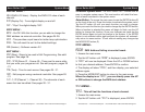
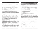
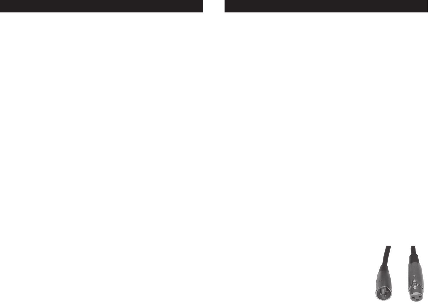
Data Cable (DMX Cable) Requirements (For DMX
and Master/Slave Operation):
The Accu Roller
250™ can be controlled via DMX-512 protocol.
The Accu Roller 250™ is a eight channel DMX unit.
The DMX address is set electronically using the
controls on the side panel of the unit. Your unit and
your DMX controller require a standard 3-pin XLR
connector for data input and data output (Figure
1). If you are making your own cables, be sure to use standard two
Accu Roller 250™ Set Up
Figure 1