


Hardware and Software Design • Manufacturing Services
P a g e 13
Register Definitions
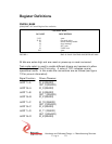
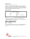
PMC4U_BASE
[0X00] PMC-4U Control Register Port read/write
CONTROL BASE
DATA BIT DESCRIPTION
31-22 spare
21-20 test mode select
19 master interrupt enable
18 force interrupt
17 SCC reset
16 UART reset
15-0 spare
FIGURE 4 PMC-4U BASE CONTROL REGISTER BIT MAP
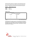
All bits are active high and are reset on power-up or reset command.
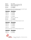
Test mode select is used to enable different drivers and receivers to allow
thorough testing of the IO circuitry. A value of “00” indicates normal
operational mode. In this mode the connections are as follows (see figure
12 for pin-out information):
Signal Function Driver/Receiver
UART Tx A IO_8 (RS422)
OUT_0 (RS423)
UART Rx A IO_0 (RS422)
UART Tx B IO_9 (RS422)
OUT_1 (RS423)
UART Rx B IO_2 (RS422)
UART Tx C IO_10 (RS422)
OUT_2 (RS423)
UART Rx C IO_4 (RS422)
UART Tx D IO_11 (RS422)
OUT_3 (RS423)
UART Rx D IO_6 (RS422)