


Hardware and Software Design • Manufacturing Services
P a g e 25
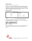
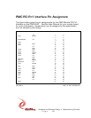
PMC PCI Pn2 Interface Pin Assignment
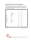
The figure below gives the pin assignments for the PMC Module PCI Pn2
Interface on the PMC-4U-IO. See the User Manual for your carrier board
for more information. Unused pins may be assigned by the specification
and not needed by this design.
+12V 1 2
34
GND 5 6
GND 7 8
910
11 12
RST# BUSMODE3# 13 14
BUSMODE4# 15 16
GND 17 18
AD30 AD29 19 20
GND AD26 21 22
AD24 23 24
IDSEL AD23 25 26
AD20 27 28
AD18 29 30
AD16 C/BE2# 31 32
GND 33 34
TRDY# 35 36
GND STOP# 37 38
PERR# GND 39 40
SERR# 41 42
C/BE1# GND 43 44
AD14 AD13 45 46
GND AD10 47 48
AD8 49 50
AD7 51 52
53 54
GND 55 56
57 58
GND 59 60
61 62
GND 63 64
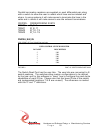
FIGURE 11 PMC-4U PN2 INTERFACE